Why a Motor Controller Trips at Startup: Inrush Current and Nuisance Tripping
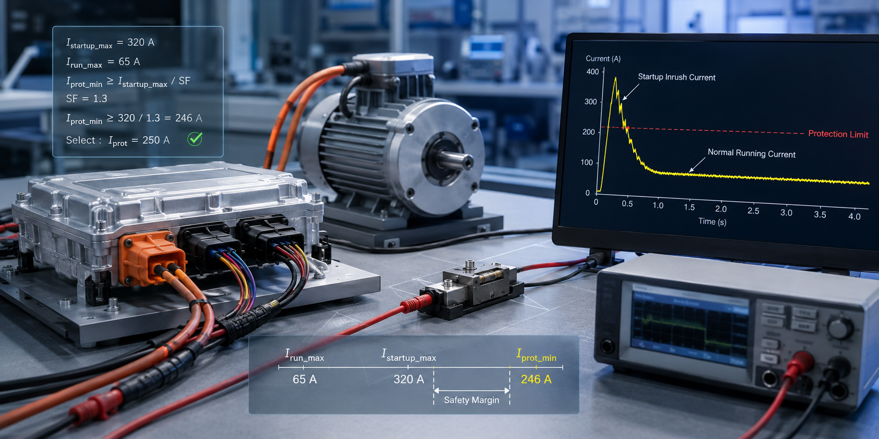
When a motor controller trips at startup, the first step is not to oversize the fuse or replace the controller; it is to characterize the first few milliseconds after the motor controller is energized. The load current at turn-on is not the steady-state current used for harness sizing. It is an inrush event driven by low initial motor impedance, DC-link capacitor charging, and a rotor at zero speed with essentially no back electromotive force (back-EMF) to oppose the supply. In many automotive motor applications, the inrush peak is 5 to 10 times the nominal running current; in brushed DC motors or drive designs with large input capacitance, the peak can be higher.The common failure mode is straightforward: an overcurrent protection device selected only against the motor nameplate or rated running current interprets the startup transient as a fault and clears, trips, or current-limits before the motor can accelerate. On the bench, the controller appears defective. Electrically, the protection element is doing what it was designed to do, but its time-current characteristic does not distinguish a valid startup transient from a true fault. In automotive motor-control programs, this is a typical nuisance-trip issue and is often discovered late in design verification or validation.
This issue is more severe in a vehicle than on a room-temperature lab supply. Ambient temperature changes both the motor load and the protection device. At -40°C, lubricant viscosity and mechanical breakaway torque increase, so the motor may draw more current during startup. At high ambient temperatures such as +85°C, or higher near an inverter, engine compartment, or power electronics module, fuse and PTC current ratings derate. The worst nuisance-trip condition can therefore occur during cold-crank or cold-start operation, while the worst continuous-current margin can occur at elevated ambient temperature.
Repeated cycling is also important. Power windows, seat adjusters, pumps, blowers, actuators, and cooling fans may experience tens of thousands to hundreds of thousands of start events over the vehicle life. Each start imposes a thermal pulse on the protection element. A device that survives one startup waveform in a demonstration may still exhibit parameter drift, resistance shift, or fatigue after life-cycle exposure.
The electrical environment is not ideal. The same 12-V or 48-V distribution rail may serve multiple loads, battery voltage can sag during crank, load-dump and other ISO 7637-2 type transients can appear on the supply, and the wiring harness introduces real resistance and inductance between the battery, controller, and load. These parasitic elements shape the actual current waveform seen by the protection device, so datasheet assumptions must be validated with the production-intent harness and supply path.
The design objective is not to oversize the protection device. Oversizing may eliminate nuisance trips, but it can also reduce the ability to clear a locked-rotor condition, winding fault, or harness short before excessive conductor, connector, or PCB heating occurs. Correct selection requires a measured current-versus-time profile, the protection device time-current curve (TCC), temperature derating, and the vehicle-level fault cases the circuit is intended to protect.
Motor Controller Trips at Startup: Electrical Characteristics to Measure
A robust protection selection begins with the motor-drive current profile rather than with the rated current alone. Four operating regions should be defined and documented for the application.1. Inrush current. Inrush is a short-duration, high-peak current event that typically occurs over a few milliseconds to several tens of milliseconds. In brushed DC motors, it is largely determined by low armature resistance at standstill. In BLDC or PMSM motor drives, DC-link capacitor charging, pre-charge implementation, and soft-start strategy can dominate the peak current. This current is expected during normal operation, so the protection device must tolerate it repeatedly without cumulative degradation.
2. Startup or acceleration current. After the initial inrush peak, the rotor is still below operating speed and back-EMF remains low. The motor therefore draws current above its steady-state value while accelerating the mechanical load. Depending on inertia, fluid load, gearing, or friction, this region may last from tens of milliseconds to more than one second. Many false-trip problems occur here because the current is lower than the inrush peak but long enough to heat fast-acting protection elements.
3. Steady-state running current. After the motor reaches speed, current settles to the normal operating range. This value must be evaluated at the worst legitimate load condition, not only at nominal load. Examples include a cooling fan with restricted airflow, a pump at high head pressure, or a window motor against a stiff seal. These operating conditions are not faults, but they reduce margin to the protection threshold.
4. Fault current. The protection device exists to manage fault conditions such as locked rotor, shorted winding, PCB short, or a harness short between the battery and controller. A locked-rotor condition is especially difficult because it can overlap the startup-current region in magnitude but persists long enough to generate damaging thermal energy in the motor, conductors, terminals, and PCB copper.
Vehicle-level conditions must then be superimposed on these four regions. Supply voltage is not fixed. In a 12-V electrical system, the rail may drop to approximately 6 to 9 V during crank and may experience positive transients during load dump. Harness impedance limits and slows fault current, which affects fuse can reach its specified clearing behavior. Temperature affects the motor torque demand, conductor resistance, semiconductor thresholds, fuse element heating, and PPTC hold/trip current.
EMI and transient behavior must also be considered. PWM switching ripple, inductive kickback when the motor is de-energized, and coupled transients from adjacent loads may not directly trip the protection device, but they can distort measurement captures and influence electronic current-limit decisions. Current measurement bandwidth, probe placement, and harness configuration should therefore be defined in the test procedure.
The practical engineering deliverable is a current-versus-time profile for the specific motor, controller, harness, and supply path. It should be captured at the relevant temperature and voltage corners and then used as the input to protection-device selection.
Balancing Startup Ride-Through and Fault Protection
The protection function must be intentionally tolerant of legitimate startup energy while remaining fast enough to clear actual faults. The key variable is time. A simple threshold-only approach will either trip during startup or fail to protect the harness and motor during a sustained overload. The correct device curve sits above the measured inrush and acceleration profile and below the thermal damage limits of the motor, wiring, connectors, and PCB.On a time-current plot, the inrush peak appears as a high-current, short-duration point. The acceleration region appears as a moderate overcurrent with longer duration. Normal running current is lower and continuous. Stall, winding short, and harness short occupy the region that must be interrupted or current-limited. A properly selected protection device rides through inrush and acceleration with margin while clearing or limiting fault current before a thermal limit is exceeded.
Different protection technologies implement this behavior in different ways. Time-delay fuses use element geometry and thermal mass to tolerate short-duration inrush energy. They are simple, cost-effective, and available with high interrupting ratings, but they are one-shot devices and require service replacement after clearing. Polymer PPTC resettable devices transition to a high-resistance state when self-heating exceeds the trip threshold and then reset after cooling; they are suitable for repetitive, self-clearing overloads but require careful derating over temperature. Electronic fuses, load switches, and smart high-side switches implement current limiting, blanking time, diagnostics, thermal shutdown, and retry or latch-off behavior in silicon, providing tighter separation between startup and fault conditions at higher cost and with additional thermal design requirements.
Across all device families, the selection levers are similar. The device must tolerate the measured inrush and acceleration energy with adequate margin at the cold corner. Its continuous hold or current rating must exceed the worst-case legitimate running current at the hot corner after derating. Its clearing time or current-limit response must protect the motor, wire gauge, terminals, connector system, and PCB copper during locked-rotor and short-circuit conditions. Finally, the interrupting rating or short-circuit rating must exceed the available fault current at the protection location.
A device is successful when its TCC maintains separation between normal motor behavior and fault behavior over the full operating environment. A curve that works only at 25°C is not sufficient for an automotive application.
Selection Calculation Example
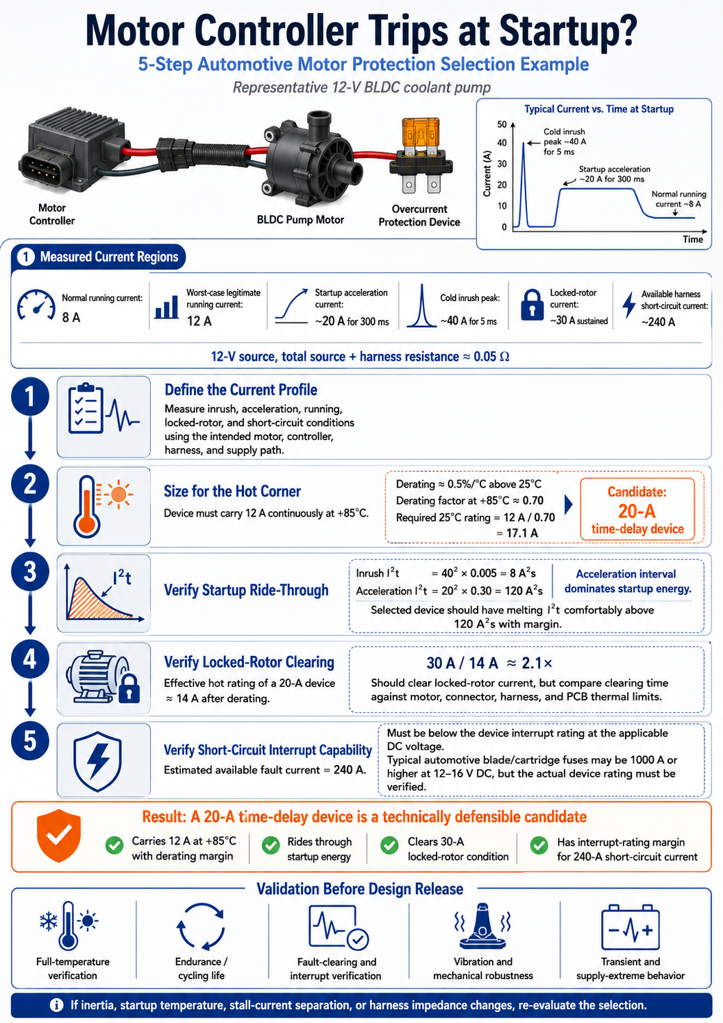
The following example uses a representative 12-V BLDC coolant pump. The numerical values are illustrative; production selection should always use measured waveforms from the intended motor, controller, harness, and supply architecture.Step 1 - Establish the measured current regions. Assume the following bench captures using the production-intent harness: nominal running current = 8 A; worst-case legitimate running current = 12 A; startup acceleration current = approximately 20 A for 300 ms; cold inrush peak from capacitor charging and breakaway torque = approximately 40 A for 5 ms; locked-rotor current = approximately 30 A sustained; available harness short-circuit current with a 12-V source and 0.05 ohm total source-plus-harness resistance = approximately 240 A.
Step 2 - Size the continuous rating at the hot corner. The protection device must carry 12 A continuously at +85°C. If a fuse element is derated by approximately 0.5% per °C above 25°C, the 60°C rise from 25°C to 85°C reduces capacity by roughly 30%, or a derating factor of 0.70. The required 25°C rating is therefore 12 A / 0.70 = 17.1 A. A 20-A time-delay device becomes a reasonable candidate.
This step is frequently missed. Selecting a 12-A device because the maximum running current is 12 A ignores hot-temperature derating and can create nuisance trips during high-load operation at elevated ambient temperature.
Step 3 - Verify startup ride-through. Evaluate the startup energy against the fuse melting I2t or the electronic device blanking/current-limit profile. The inrush pulse is approximately 40^2 x 0.005 = 8 A2s. The acceleration interval is approximately 20^2 x 0.30 = 120 A2s and is therefore the dominant startup energy. If the selected 20-A time-delay fuse has a melting I2t comfortably above this value with margin, it should ride through startup. This must still be confirmed at cold temperature with the actual motor and harness.
Step 4 - Verify locked-rotor clearing. At +85°C, the effective rating of a 20-A device may be approximately 14 A after derating. A 30-A locked-rotor current is therefore about 2.1 times the hot effective rating. The device should clear, but the clearing time must be compared against the motor winding, harness, connector, and PCB thermal limits. If locked-rotor current is too close to acceleration current, a fuse alone may not provide sufficient discrimination; an electronic protection device with programmable blanking time and current limit may be required.
Step 5 - Verify short-circuit interrupt capability. The estimated 240-A available short-circuit current must be below the rated interrupting capacity of the selected device at the applicable DC voltage. Many automotive blade or cartridge fuses have interrupt ratings of 1000 A or higher at 12 to 16 V DC, but the actual device rating must be verified. Also confirm the low-impedance case of a short at the connector or at the controller input.
For this example, a 20-A time-delay device is a technically defensible candidate: it carries 12 A at the hot corner with derating margin, rides through the 120 A2s startup energy, clears a 30-A locked-rotor condition with reasonable multiple of rating, and has sufficient interrupt-rating margin for the calculated short-circuit current. If any input changes - higher inertia, colder startup, lower stall current separation, or lower harness impedance - the selection must be re-evaluated.
Key Reliability Validation Points
A calculation identifies a candidate device. Validation confirms whether that device is acceptable for the vehicle environment and the application mission profile. The following tests should be included before design release.Full-temperature verification. Repeat startup, running-current, stall, and short-circuit evaluations at the cold and hot operating corners. Confirm that the device rides through cold-start inrush while still carrying worst-case continuous load at elevated ambient after derating. Plot the measured waveform against the applicable TCC at each temperature corner.
Endurance and cycling life. Motor loads may start thousands or hundreds of thousands of times over the vehicle life. For PPTC and electronic protection devices, repeated trip/reset or current-limit cycling can shift parameters. Run cycling tests at worst-case duty cycle and ambient temperature, then re-measure hold current, trip current, resistance, response time, and leakage or standby behavior as applicable.
Fault-clearing and interrupt verification. Validate the device against realistic faults: connector-level dead short, locked rotor held until timeout or trip, winding fault, and intermediate overload. Confirm safe clearing or current limiting with no arcing, package rupture, PCB damage, connector overheating, or harness insulation damage.
Vibration, shock, and mechanical robustness. Fuse holders, solder joints, terminals, welded elements, and PCB pads are exposed to vibration and thermal cycling. Validate the device and mounting method against the vibration and mechanical shock profile appropriate for the installation location. Include post-test resistance and continuity checks to detect intermittent opens or high-resistance faults.
Transient and supply-extreme behavior. Verify operation during cold crank, load dump, reverse polarity if applicable, PWM switching, inductive kickback, and coupled conducted transients. The protection device should not false-trip under defined transients, and the protection strategy must remain safe during supply undervoltage and overvoltage conditions.
Application validation and component qualification should be documented separately. Passing the above tests demonstrates suitability for a specific automotive application. It is not equivalent to a formal automotive-grade qualification unless the component has passed a defined standard or test sequence such as the applicable AEC-Q requirement and the supplier provides documentation. The design file should distinguish between application-level validation evidence and component-level qualification claims.
FAQ
Why does the motor controller trip immediately at startup even though the running current is below the fuse rating?
The most likely cause is motor inrush current or DC-link capacitor charging. At turn-on, the motor may draw 5 to 10 times its running current for a short duration while the rotor is at standstill and back-EMF is near zero. A device selected only for running current can interpret that transient as a fault. Select using the measured current-versus-time startup profile and the protection device TCC, not by nameplate current alone.Should automotive motor protection use a fast-acting fuse or a time-delay fuse?
Most motor loads require a time-delay characteristic because startup current is a normal, repetitive event. A fast-acting fuse is more appropriate for loads with minimal inrush and a relatively flat current profile. For motor drives, the selected device must ride through startup while still clearing locked-rotor and short-circuit faults within the thermal limits of the system.How does temperature affect overcurrent protection selection?
Temperature affects both the motor and the protection device. Low temperature increases mechanical drag and startup current. High temperature reduces fuse and PPTC current capability through derating and changes semiconductor thresholds or thermal shutdown behavior in electronic protection devices. Selection must therefore be verified at both cold and hot corners, not only at 25°C.How can nuisance tripping be prevented without reducing fault protection?
Separate normal startup and fault behavior in the time domain. Measure the motor current profile across voltage, temperature, and load conditions, then select a device whose curve is above the legitimate inrush and acceleration waveform but below the stall and short-circuit damage limits. If startup current and stall current are too close for a fuse to discriminate, use electronic protection with controlled blanking time, current limiting, and fault diagnostics.Does an automotive motor application always require an automotive-grade protection component?
The terminology should be precise. A component that is suitable for an automotive application has been validated in that application. A component that is automotive-grade has passed a specified automotive qualification or standard supported by supplier documentation. These are not interchangeable claims. Supplier qualification evidence and customer application validation should both be retained in the design record.What is the most common protection-selection mistake?
The most common mistake is selecting the device from maximum running current alone while ignoring startup inrush and hot-temperature derating. The result is nuisance tripping at high load or elevated ambient temperature. Increasing the rating without analysis may eliminate the nuisance trip but can compromise locked-rotor or harness-short protection.Do load dump, cold crank, or conducted transients trip motor protection devices directly?
They may not trip the protection device directly, but they affect the waveform and operating margin. Cold crank can increase startup current, load dump can stress electronic protection and downstream components, and PWM or inductive transients can distort measurements. Validation should use the real harness, supply path, and transient conditions defined for the vehicle platform.Conclusion
Motor protection is a discrimination problem, not a simple current-threshold problem. The protection strategy must tolerate all legitimate motor behavior - inrush, cold breakaway, acceleration, and worst-case running load - while clearing or limiting real faults such as locked rotor, winding short, PCB short, and harness short before thermal damage occurs. That discrimination must remain valid across temperature, supply variation, harness impedance, vibration, transient exposure, and life-cycle operation.
For this reason, the correct answer to a motor controller that trips at startup is rarely to install a larger fuse. Oversizing may mask the symptom while reducing fault-clearing performance. The correct engineering process is to measure the actual current-versus-time profile, select a time-delay, resettable, or electronic protection device with documented margin, and validate the device under the relevant automotive environmental and fault conditions.
Documentation should also distinguish application suitability from formal component qualification. A part validated in the motor system is suitable for that specific design; a part described as automotive-grade should be supported by named qualification standards and supplier records. Long-term availability, change notification, and construction consistency should also be treated as reliability factors because any later substitution can force re-selection and re-validation.
For motor systems that trip at startup, operate near the boundary between acceleration current and locked-rotor current, or require operation over demanding temperature and vibration conditions, the protection selection should be reviewed using the measured startup profile, fault-current assumptions, harness impedance, mission profile, and qualification requirements. A well-selected protection device is one that remains electrically correct, thermally safe, and commercially available throughout the vehicle production life.
Automotive-grade PPTC product series
Fuzetec PPTC Resettable Fuse with IATF 16949 and AEC-Q200 Compliance
How to select your overcurrent protection fuse
Find TVS diode product!
Contact us!