
Can’t Make Sense of the Data Center Power Architecture? Which Layer Do Protection Devices Belong In?
Executive Summary
AI servers are pushing data center power to unprecedented density. A single rack now draws around 120 kW, with the next generation heading toward 1 MW, and individual GPU superchips consuming power measured in kilowatts. As current levels scale up, so does the destructive potential of every surge, overcurrent, or short circuit. The real question is no longer whether to protect the system, but which layer of the power chain each protection device belongs in — and which type to use.This article walks the full power chain from grid to chip, breaks down the protection requirements at each layer and the logic behind device selection, and explains the design trade-offs under high power density and the emerging 800 VDC architecture — helping system engineers place protection where it matters.
The Power Chain from Grid to Chip
To decide where protection devices go, you first need to see where the power comes from and how many conversions it passes through. Using a mainstream AI rack as an example, the power chain breaks down into five layers:- Grid and facility distribution: Medium-voltage utility power is transformed and passed through UPS/BBU, then enters the data hall as three-phase 400/480 VAC (400 V in EU regions, 480 V in North America).
- Rack distribution: PDUs and busbars deliver power to each rack. An NVIDIA GB200 NVL72 rack is built from four 30 kW power shelves for a total draw of roughly 120 kW (the newer GB300 NVL72 draws more).
- Power supply (PSU) stage: Inside the power shelf, 400/480 VAC is rectified into 48–54 VDC (54 V on NVIDIA GB200) — the focal point for AC-DC conversion and first-line surge protection.
- Board-level DC distribution: On the compute board, VRMs/POL converters step 48–54 V down to 12 V and then to the ~0.6–0.8 V the chip needs — a low-voltage, very-high-current environment.
- Chip stage: GPU/CPU superchips, with a single device exceeding 1,000 W and the GB200 superchip reaching roughly 2,700 W.
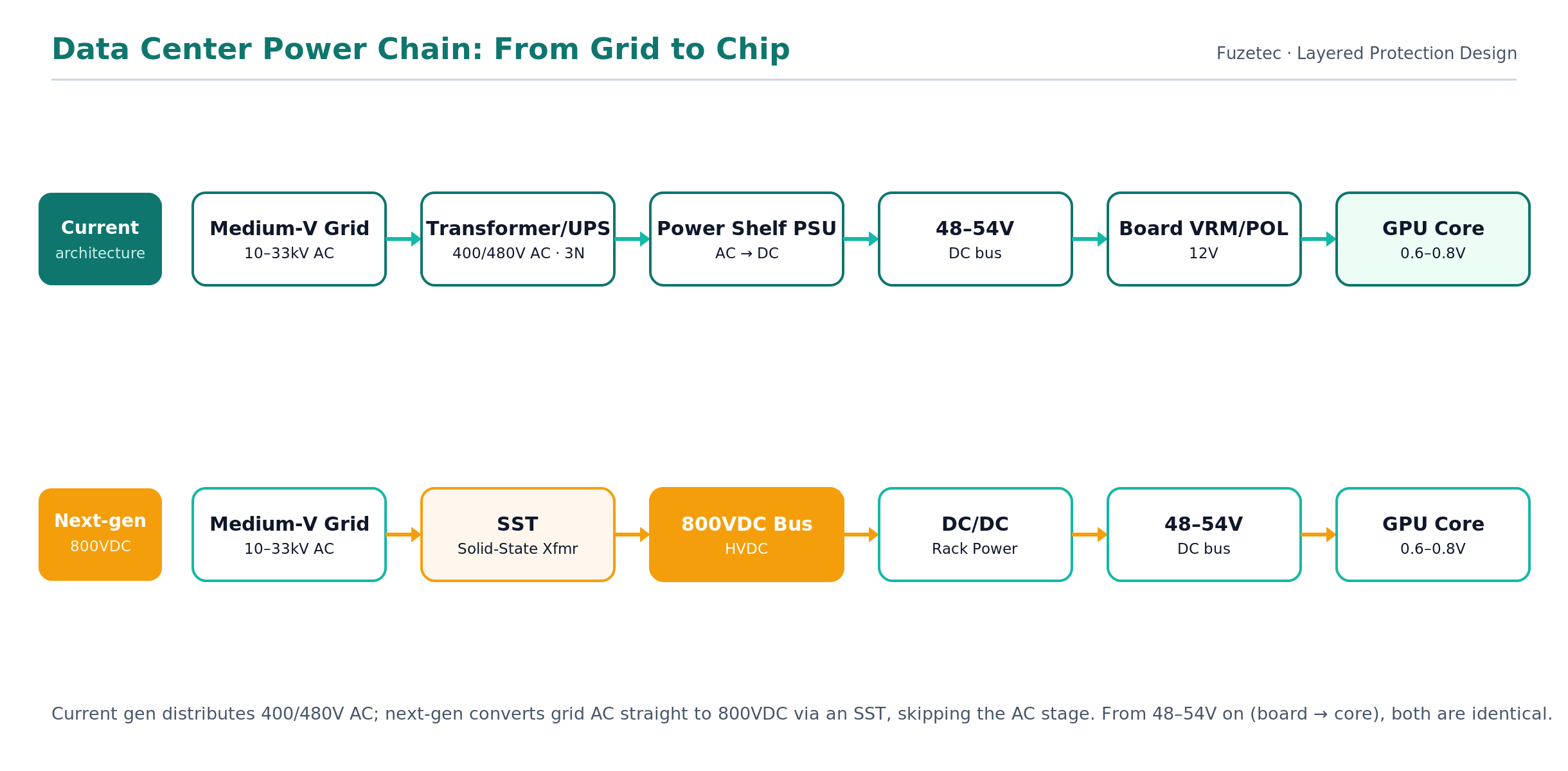
Figure 1. Data center power chain — current 400/480 VAC vs. next-gen 800 VDC (illustration by Fuzetec).
Protection Needs at Each Level
PSU Side
The input of the power shelf faces the grid directly, and its greatest threats are surge and overvoltage: lightning-induced transients, grid switching, and load steps can all inject high-energy pulses at the input. Protection here is about absorbing large energy and clamping overvoltage — typically a metal-oxide varistor (MOV) to take the surge energy, a TVS diode for fast overvoltage clamping, and an input fuse as the final overcurrent and short-circuit disconnect.In addition, the large bulk electrolytic capacitors in a power shelf draw a heavy inrush current at power-up, and data center power shelves must support hot-swap. A MOSFET paired with a hot-swap controller is therefore commonly used for inrush limiting and soft-start, preventing the power-up surge from collapsing the busbar voltage or damaging the contacts.
Board-Level Protection
Once on the board, voltage has dropped below 54 V, but current has scaled up to hundreds of amperes. Faults here are characterized as low-voltage, high-current, and fast-acting: if a POL rail shorts or a load misbehaves, even millisecond-level delays can burn copper traces or destroy the chip.Board level therefore favors devices that are small, fast, and self-resetting: a resettable fuse (PPTC) trips on overcurrent or overtemperature and recovers on its own once the fault clears, sparing the data center from replacing fuses board by board; eFuses and electronic protection ICs integrate precise overcurrent, overvoltage, overtemperature, and soft-start; and low-clamping-voltage TVS devices protect surge-sensitive signal and power nodes. The closer to the chip, the lower the clamping voltage and the faster the action must be.
The Deployment Logic of Protection Devices
The core principle of layered protection is a clear division of labor with coordination between stages:- Upstream blocks energy, downstream delivers speed: layers closer to the grid absorb and shunt large-energy events such as surges, while layers closer to the chip cut off localized faults quickly and precisely.
- Clamping voltage descends layer by layer: upstream tolerates higher let-through voltage, while downstream requires low clamping to protect fragile low-voltage components.
- Selectivity: the device closest to the fault should act first, isolating the impact to the smallest possible area rather than tripping an entire rack or power shelf.
- Serviceability first: data centers cannot easily go offline to swap parts, so the deeper into the system, the more you favor self-resetting (PPTC) or resettable (eFuse) devices to minimize maintenance downtime.
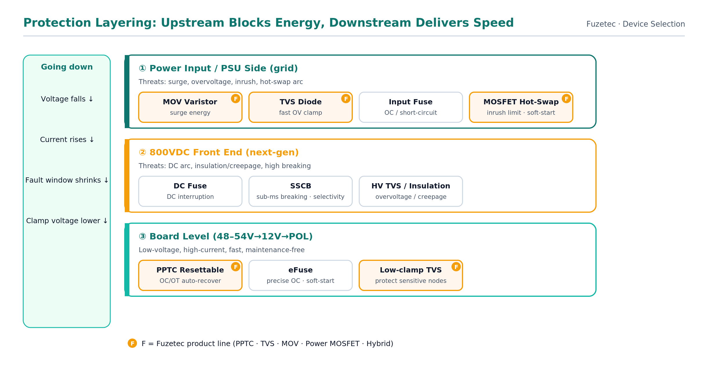
Figure 2. Protection layering and device selection; the “F” badge marks Fuzetec’s product line (illustration by Fuzetec).
Design Trade-offs
Under AI-class power density, protection design offers no free lunch. Engineers typically balance the following trade-offs:- Clamping voltage vs. let-through: lower clamping is safer for downstream stages but increases the power and physical burden on the device.
- Speed vs. nuisance tripping: too slow and protection arrives late; too sensitive and normal transients cause nuisance trips that hurt availability.
- On-resistance / insertion loss vs. protection level: any device in the main current path adds I²R loss and heat, and in high-current environments that cost is amplified and must be evaluated alongside thermal design — mainstream AI racks are now liquid-cooled (cold plates, coolant distribution units) with a target PUE below 1.2, so a protection device’s heat must fit within that thermal budget.
- One-time vs. resettable: one-time fuses are low-cost but must be replaced; resettable and electronic devices cost more but sharply reduce data center maintenance.
FAQ
Q: Does adding more protection devices make a system more reliable?A: No. Over-stacking protection adds insertion loss, failure points, and cost, and can even break coordination. The right approach is to follow the layering logic and place the appropriate type and quantity at each layer.
Q: How does the 800 VDC architecture affect protection device selection?
A: As DC voltage rises, DC surge, DC arcing, and insulation risks all increase. Voltage ratings, breaking capacity (especially DC interruption), and clamping design must all be re-evaluated — you cannot simply reuse low-voltage AC selections.
Q: Is an eFuse mandatory at board level?
A: Not necessarily. eFuses offer integrated, precise protection with soft-start, ideal for nodes with tight overcurrent-threshold and timing requirements. Where only basic overcurrent/overtemperature is needed and self-recovery and cost matter, a PPTC resettable fuse is often a better fit — and the two are frequently used together.
Q: What protection step is most easily overlooked under high power density?
A: Inrush current and hot-swap soft-start. The heavy current at power-up is often underestimated, yet it is a common cause of collapsed busbar voltage and damaged contacts and MOSFETs.
Conclusion & Architecture Consultation
The power challenge of the AI data center is, at heart, a reliability-engineering problem of falling voltage, rising current, and shrinking fault tolerance. The value of a protection device lies not in quantity but in whether it sits at the right layer and is the right type: upstream absorbs large energy, downstream cuts off faults quickly and precisely, clamping drops as you approach the chip, all while balancing speed, loss, and maintenance cost.Fuzetec Technology has specialized in circuit protection since 1997, with a portfolio spanning PPTC resettable fuses, TVS diodes, MOV varistors, power MOSFETs, and hybrid protection solutions, all built to AEC-Q200 and IATF 16949 automotive and quality standards. If you are planning the protection layering for AI servers, power shelves, or high-power-density boards, contact us — our engineering team can help evaluate device selection and coordination across every layer.
Architecture consultation & selection support: www.fuzetec.com | Tel: +886-2-8990-2113