
TVS Diode Selection: Protecting Sensitive Circuits From Voltage Spikes You Can't See Coming

A TVS (Transient Voltage Suppressor) diode is a semiconductor protection device that clamps voltage spikes on a circuit to a safe level within nanoseconds, protecting downstream components from transient overvoltage events such as electrostatic discharge, inductive load switching, or lightning-induced surges on external cabling. Selecting the right TVS diode requires matching several parameters — standoff voltage, clamping voltage, peak pulse power, and response time — to both the normal operating voltage of the protected circuit and the expected characteristics of the transient event being guarded against.
TVS diodes are one part of a broader protection strategy. Engineers can also explore Fuzetec’s overvoltage protection solutions based on the transient type and application requirements.
A TVS diode normally presents very high resistance and has minimal effect on circuit operation at normal operating voltages. When a voltage transient exceeds the device's breakdown voltage, the TVS diode rapidly switches to a low-impedance state, shunting the excess current away from the protected circuit and clamping the voltage to a defined maximum level until the transient energy has dissipated. This switching action happens in picoseconds to low nanoseconds, making TVS diodes suitable for protecting against extremely fast transient events that slower protection devices, such as some gas discharge tubes, cannot respond to in time on their own.| Parameter | What It Defines |
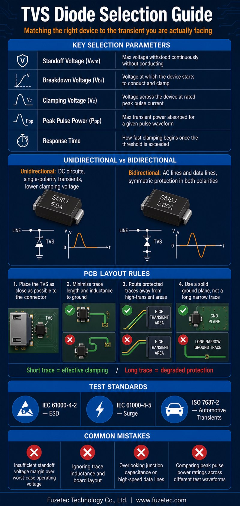
| Standoff voltage (Vwm) | The maximum voltage the device can withstand continuously without conducting significantly |
| Breakdown voltage (Vbr) | The voltage at which the device begins to conduct and clamp |
| Clamping voltage (Vc) | The maximum voltage across the device during a specified peak pulse current condition |
| Peak pulse power (Ppp) | The maximum transient power the device can absorb without damage for a given pulse waveform |
| Response time | How quickly the device begins clamping once a transient exceeds its threshold |
Unidirectional Devices
Unidirectional TVS diodes conduct in only one direction under transient conditions and are appropriate for DC circuits where voltage transients of concern occur in only one polarity relative to the protected circuit's normal operation, offering a somewhat lower clamping voltage than a comparable bidirectional device.Bidirectional Devices
Bidirectional TVS diodes provide symmetric protection in both directions and are typically used on AC lines or data lines where transients could occur in either polarity relative to the signal's normal operating range. Peak pulse power ratings are specified against a particular standardized test waveform, most commonly an 8/20 microsecond or 10/1000 microsecond pulse depending on the relevant industry standard, and the actual transient event a circuit needs protection against may have a meaningfully different waveform shape and duration than the standard test condition. Engineers should confirm which waveform standard applies to their specific application — such as IEC 61000-4-5 for AC mains surge protection — and select a device rated against the appropriate test waveform rather than assuming all peak pulse power ratings are directly comparable across different standards or manufacturers.- ESD protection on I/O connectors and user-accessible interfaces such as USB and HDMI ports
- Automotive electronics protection against load dump and inductive switching transients
- Communication line protection against lightning-induced surges on external cabling
- Power supply input protection against line transients and switching noise
- Place the TVS diode as close as physically possible to the connector or interface being protected
- Minimize trace length and inductance between the TVS diode and ground to ensure fast, effective clamping response
- Route protected signal traces away from noisy or high-transient-risk areas of the board where practical
- Use a solid ground plane connection for the TVS diode's ground path rather than a long, narrow trace
| Package Type | Typical Application |
| Small-outline SMD (e.g., SOD-523, SOT-23) | Space-constrained signal and data line protection |
| Larger SMD packages (e.g., SMB, SMC) | Higher power applications with moderate board space constraints |
| Axial leaded packages | High peak pulse power applications such as AC mains and industrial equipment protection |
After determining the required working voltage, clamping voltage, peak pulse power, and package size, compare the available Fuzetec TVS diode product series to identify suitable options. For applications with multiple signal lines requiring protection — such as a multi-pin connector or a parallel data bus — TVS diode array devices integrate multiple protection elements into a single package, reducing board space and simplifying layout compared to placing individual discrete TVS diodes on each line. Array devices are particularly common in USB, HDMI, and other multi-conductor interface protection applications where board space is at a premium and per-line protection consistency is important. TVS diodes exhibit junction capacitance that can degrade signal integrity on high-speed data lines if not properly accounted for during selection, since excessive capacitance can attenuate or distort fast edge-rate signals passing through the protected line. Applications involving high-speed data interfaces should specifically evaluate low-capacitance TVS diode variants designed for signal integrity preservation, rather than defaulting to a general-purpose device selected primarily for its power handling capability alone. Different industries and applications reference different standardized transient test protocols, and confirming which standard applies to a given design early in the selection process helps ensure the TVS diode's published ratings are actually relevant to the real-world threats the product will face.
- IEC 61000-4-2 covers electrostatic discharge (ESD) testing relevant to human-body-model contact and air discharge events
- IEC 61000-4-5 covers surge immunity testing relevant to AC mains and long-cable transient events
- ISO 7637-2 covers automotive electrical transient testing relevant to load dump and switching transients in vehicle electronics
- Telecommunications equipment often references industry-specific lightning surge standards for line-side protection
- Selecting standoff voltage without adequate margin above realistic worst-case operating voltage, including tolerance and ripple
- Overlooking board layout and trace inductance, undermining an otherwise correctly specified device's actual clamping performance
- Ignoring junction capacitance effects on high-speed signal lines, leading to signal integrity problems
- Assuming peak pulse power ratings are directly comparable across devices tested against different standardized waveforms
- Share the protected circuit's normal operating voltage range, including worst-case tolerance and ripple, with the supplier
- Identify which transient test standard applies to your specific application and target compliance requirement
- Discuss board layout constraints and space availability near the protected connector or interface
- Request sample devices for validation testing under conditions representative of actual field use before finalizing a design
As electronic devices continue to face an expanding range of transient threats from both external cabling and internal switching noise, thoughtfully specified TVS diode protection remains one of the most cost-effective ways to improve overall product reliability and reduce field failures traceable to voltage transient damage. Involving supplier application engineering support and validating designs against the actual relevant test standard both meaningfully reduce the risk of discovering protection gaps only after a product has already reached the field.
Ultimately, transient voltage protection deserves the same rigorous, application-specific design attention given to any other critical circuit element, since the cost of an inadequately protected design is almost always far higher than the incremental cost of properly specifying protection components upfront.


