Why Overcurrent Protection Device Selection Mistakes Surface at Mass Production
In overcurrent protection device selection, one of the most frustrating problems is that the wrong part often looks acceptable during early engineering validation, but fails after the product enters pilot run or mass production. On the lab bench, the circuit may power up normally, pass a few functional tests, and survive limited short-circuit checks. The engineer may see no obvious issue and assume the PPTC, fuse, or other protection component has been selected correctly. However, once hundreds or thousands of units are built, the hidden margin problems begin to appear: unexpected trips, delayed protection, abnormal heating, unstable startup, or even customer returns from the field.The reason is simple: early testing usually represents only a narrow slice of real operating conditions. A prototype is often tested at room temperature, with a stable power supply, short cable length, limited load variation, and carefully assembled boards. Mass production is different. Component tolerances, PCB copper variation, connector resistance, power adapter variation, motor startup current, battery voltage range, ambient temperature, and user behavior all begin to stack together. A protection part that barely passed in the lab may no longer have enough design margin when these variables shift in the wrong direction.
For example, a PPTC selection may look correct if the engineer only compares the normal working current with the hold current at 25°C. But the hold current is not a fixed value under all conditions. As ambient temperature rises, the PPTC’s available hold current decreases. If the equipment operates inside a sealed enclosure, near a heat source, or in an automotive or industrial environment, the actual operating temperature may be far above room temperature. A part that can hold 1.0 A at 25°C may not reliably hold the same current at 60°C or 85°C. This is why skipping temperature derating is one of the most common PPTC selection errors.
Another reason for selection mistakes is that engineers sometimes focus only on current while overlooking voltage and fault energy. Overcurrent protection is not just about choosing a device with the right hold current and trip current. The maximum working voltage, rated voltage, interrupting capability, resistance, trip time, thermal environment, and coordination with upstream and downstream circuits must also be reviewed. If the rated voltage is too low, or if the device cannot safely handle the available fault current, the circuit may pass normal operation but fail under abnormal conditions.
Mass production also exposes startup and transient behavior that may not be obvious in a single prototype test. Motors, capacitive loads, DC-DC converters, and battery-powered systems can produce inrush current that is much higher than steady-state current. If the protection device is selected too close to the normal operating current, it may nuisance trip during startup. On the other hand, if the device is oversized to avoid nuisance trips, it may respond too slowly during a real fault. This balance between avoiding false trips and still providing effective protection is where many overcurrent protection device selection problems begin.
A good selection process should therefore not ask only, “What is the normal current?” It should ask, “What is the full current profile across temperature, voltage, tolerance, startup, overload, and fault conditions?” The protection component should be selected based on the worst-case operating window, not the most convenient lab condition. This is especially important for products shipped globally, where the same design may be used in different climates, power grids, installation environments, and customer usage patterns.
In practical application engineering, most batch return issues related to protection parts come from insufficient margin, not from a completely random component failure. The device did exactly what its characteristics allowed it to do, but the selection logic did not fully match the real application. That is why engineers should treat protection device selection as a system-level decision, not a simple part-number lookup. Before releasing a design to production, it is essential to review hold current, trip current, temperature derating, rated voltage, maximum fault current, response time, resistance impact, and reset behavior. A few extra checks during design-in can prevent weeks of troubleshooting, delayed shipments, and costly field returns later.
Overcurrent Protection Device Selection: Current and Temperature First
When engineers begin overcurrent protection device selection, the first instinct is usually to look at the normal working current. That is understandable. Current is the most visible parameter in the circuit, and most datasheets organize product series by hold current, trip current, rated current, or fuse current rating. However, in real application engineering, starting with working current alone is not enough. The better first step is to define the working current together with the actual ambient temperature range. These two parameters must be reviewed as a pair, not as separate checks.For a PPTC device, the hold current is typically specified at 25°C. This means the device can continuously carry that current under a defined room-temperature condition without tripping. But the product in the field rarely operates at 25°C continuously. A power adapter may run inside a plastic enclosure. A motor controller may be installed near a heat source. An automotive module may operate under the dashboard, near the battery pack, or inside an engine-adjacent environment. Industrial equipment may sit in a control cabinet where the internal temperature is much higher than the surrounding room. Under these conditions, the available hold current of a PPTC decreases as temperature increases.
This is why an engineer should not simply ask, “The circuit current is 800 mA, so can I choose an 800 mA hold-current device?” The more accurate question is, “At the highest operating ambient temperature, can this device still hold the maximum continuous working current with enough margin?” If the answer is no, the part may pass bench testing but nuisance trip during production burn-in, high-temperature testing, or field operation.
The same logic applies when evaluating a traditional fuse, although the behavior is different. A fuse does not reset like a PPTC, but it is still affected by current, ambient temperature, time-current characteristics, and installation conditions. If the rated current is selected too close to the normal operating current, the fuse may age prematurely or open during temporary overload or startup surge. If it is selected too high, it may not provide enough protection during an actual fault. Therefore, whether the design uses a PPTC, one-time fuse, or other overcurrent protection device, current must always be judged in the context of temperature and time.
A practical selection process starts by mapping the current profile of the application. The engineer should identify the steady-state current, peak startup current, inrush duration, overload current, short-circuit current, and any repetitive pulse conditions. For example, a motor load may draw several times its rated current at startup. A capacitive input may create a short but high inrush current. A battery-powered device may see different current levels at full charge, low voltage, or during charging. These details determine whether the protection component will remain stable during normal operation and still react properly during abnormal conditions.
After the current profile is understood, the ambient temperature range should be applied immediately. The device should be checked at the highest expected operating temperature, not just room temperature. For PPTC selection, this means using the manufacturer’s temperature derating curve to confirm that the selected part can hold the required current at the worst-case temperature. For fuse selection, it means checking whether derating is needed based on the installation environment and expected continuous load. This step often reveals that the first candidate part is too small, even though it appeared correct at 25°C.
The key point is that overcurrent protection device selection is not a one-dimensional current comparison. A good selection starts with a combined view of current, temperature, and operating duration. Working current tells you how much load the device must carry. Ambient temperature tells you how much protection margin remains. Startup and fault behavior tell you whether the device will trip at the right time. When these factors are reviewed together, the selection becomes much more reliable and the risk of production-stage failures is greatly reduced.
Relationship between hold current and trip current
In PPTC selection, hold current and trip current are often the first two numbers engineers compare, but they are also two of the most commonly misunderstood parameters. Hold current, usually written as IH, is the maximum current the PPTC can carry continuously without tripping under specified conditions, typically at 25°C. Trip current, usually written as IT, is the current level at which the device is expected to transition into a high-resistance state and limit the fault current.
The important point is that IH and IT are not exact switching thresholds like a digital on/off signal. There is a transition region between them. If the operating current is below IH, the device should remain in the low-resistance state. If the current reaches or exceeds IT, the device should trip. But if the current falls between IH and IT, behavior depends on temperature, duration, thermal layout, airflow, PCB copper area, and part tolerance.
This is why selecting a PPTC only by matching the normal working current to IH can be risky. The engineer must confirm that the maximum continuous current stays safely below the derated IH, while the expected fault current is high enough to exceed IT within the required protection time. A good design leaves margin on both sides: enough hold margin to avoid nuisance trips, and enough trip margin to ensure the device reacts when a real fault occurs.
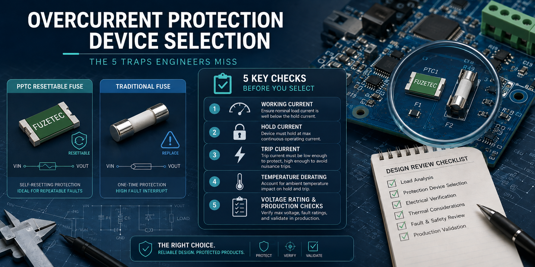
5 Most Overlooked Overcurrent Protection Device Selection Traps
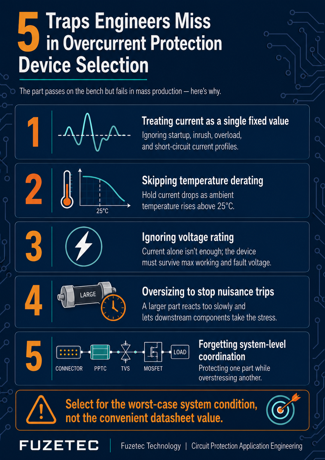
Most overcurrent protection selection errors are not caused by engineers ignoring the datasheet. They are usually caused by reading only the first few parameters and assuming the rest of the application conditions will stay close to the lab setup. In real product development, the part that looks correct on paper may still fail if the selection process does not include temperature, voltage, startup behavior, resistance impact, and fault coordination. These are the areas where protection components tend to create problems after pilot run, qualification testing, or mass production.The first trap is treating the normal working current as a single fixed value. Many circuits do not operate at one clean current level. A motor may have a low steady-state current but a much higher locked-rotor or startup current. A DC-DC converter may draw a short inrush pulse when input capacitors charge. A battery-powered device may behave differently when the battery is fully charged, deeply discharged, or connected to a charger. If the engineer selects the protection device only around the typical current, the part may nuisance trip during startup or fail to trip fast enough during an actual abnormal condition. The correct approach is to define the full current profile, including continuous current, peak current, inrush duration, overload current, and short-circuit current.
The second trap is skipping temperature derating. This is especially important for PPTC selection because hold current decreases as ambient temperature increases. A device that can hold a certain current at 25°C may not hold the same current at 60°C, 70°C, or 85°C. This becomes critical in sealed enclosures, automotive modules, industrial cabinets, battery packs, adapters, LED drivers, and motor-control systems. If temperature derating is not checked early, the design may pass room-temperature bench testing but fail during high-temperature operation or production burn-in.
The third trap is ignoring the voltage rating and maximum operating voltage. Some engineers focus heavily on current and assume voltage is only a secondary parameter. That assumption is dangerous. The protection device must be rated for the maximum voltage it may see during normal and abnormal operation. In AC input, DC bus, battery, communication line, or charger applications, voltage margin matters. If the selected part has insufficient rated voltage, it may not safely withstand the system condition during a fault. Overcurrent protection device selection must always confirm both current and voltage suitability.
The fourth trap is oversizing the protection device to avoid nuisance trips. This is a common reaction after an early sample trips unexpectedly. The engineer moves to a larger hold-current part, the nuisance trip disappears, and the design seems fixed. But oversizing may create a different problem: the device may respond too slowly during a real fault, allowing connectors, PCB traces, cables, MOSFETs, ICs, or batteries to see excessive stress. A protection component should not be selected only to stay invisible during normal operation. It must also provide meaningful limitation during abnormal operation.
The fifth trap is forgetting system-level coordination. A PPTC, fuse, TVS diode, MOV, MOSFET, power supply, connector, PCB trace, and load are not independent parts. Their behavior overlaps during fault conditions. For example, a downstream short may require the overcurrent device to trip before a power IC exceeds its thermal limit. A surge event may require coordination between an overvoltage device and an overcurrent limiter. A resettable fuse may protect a port, but its resistance may also affect voltage drop during normal operation. If the protection device is selected without reviewing the surrounding circuit, the design may protect one component while stressing another.
The practical lesson is that selection errors usually happen in the gap between “datasheet parameter” and “real application condition.” A reliable selection process should not stop at finding a device with a matching hold current. It should verify derated hold current, trip current, voltage rating, resistance range, time-to-trip curve, fault current availability, ambient temperature, load behavior, and protection coordination. When these five traps are reviewed before release, the chance of batch return caused by selection error drops significantly.
Skipping temperature derating
Skipping temperature derating is one of the fastest ways to create a PPTC selection error. Many engineers begin by checking whether the normal operating current is lower than the device’s hold current at 25°C. That is only the starting point, not the final decision. PPTC hold current decreases as ambient temperature increases, because the device is already closer to its trip condition in a hotter environment. In other words, a part that looks safe at room temperature may become marginal inside a sealed enclosure, near a motor, beside a power MOSFET, or in an industrial control cabinet.A practical review should always ask: what is the highest temperature around the protection device, not just the highest room temperature outside the product? The answer may include heat from nearby components, PCB copper layout, enclosure design, airflow, and continuous load current. For mass production, this matters because small tolerance differences can push some units over the edge. The result is often nuisance tripping during burn-in, thermal chamber testing, or field operation. Proper PPTC selection should therefore use the derated hold current at the worst-case operating temperature, with enough margin for component tolerance and thermal rise.
Ignoring max working voltage and rated voltage
Another common selection trap is treating overcurrent protection as a current-only decision. Current is important, but voltage rating is just as critical. Every overcurrent protection device has a maximum working voltage or rated voltage limit, and that limit must be higher than the maximum voltage the circuit can experience during normal operation and abnormal conditions. If the voltage rating is too low, the device may not safely interrupt, limit, or withstand the fault condition, even if the current rating appears correct.This mistake often appears in applications such as battery packs, adapters, motor controllers, DC bus lines, AC input circuits, communication ports, and charger interfaces. Engineers may select a PPTC or fuse based on hold current, then later discover that the system voltage, open-circuit voltage, surge condition, or fault voltage exceeds the device rating. That is a serious selection error because the protection part may fail before it can protect the circuit. A reliable design review should confirm maximum operating voltage, rated voltage, maximum fault current, and the device’s ability to survive the expected abnormal condition. In protection design, the correct part is not the one that only matches current; it is the one that matches current, voltage, temperature, and fault energy together.
Overcurrent Protection Device Selection Checklist
A reliable overcurrent protection device selection process should be repeatable. If the decision depends only on memory or a quick comparison of hold current, the design review will miss important details. The best approach is to use a checklist that forces the engineer to verify the application conditions, device ratings, and system-level protection behavior before the design is released to pilot run or mass production.Start with the normal operating current. Record the maximum continuous current, not only the typical current. If the circuit normally draws 800 mA but can reach 950 mA under low input voltage, high load, or aging conditions, the selection should be based on the higher value. For PPTC selection, the derated hold current must remain higher than this maximum continuous current at the worst-case operating temperature. For a fuse, the rated current and time-current curve must support continuous operation without premature opening.
Next, define the complete current profile. This includes startup current, inrush current, repetitive pulse current, overload current, locked-rotor current, and short-circuit current. Many selection errors happen because the engineer checks only steady-state current. A motor, capacitive load, battery charger, or DC-DC converter may produce a short high-current event that is normal for the system. The protection device should tolerate this normal transient without nuisance tripping, but still respond fast enough when the current represents a real fault.
The third checkpoint is ambient temperature. Do not use room temperature as the default assumption unless the product truly operates at room temperature. Review the highest local temperature around the protection component. This may be higher than the external environment because of nearby MOSFETs, regulators, transformers, motors, batteries, or limited airflow. For PPTC devices, apply the temperature derating curve and confirm that the selected part still has enough hold-current margin at the worst-case temperature. For fuses, check the manufacturer’s derating guidance and confirm that the fuse will not age or open under normal thermal stress.
The fourth checkpoint is voltage rating. Confirm the maximum working voltage, rated voltage, and possible abnormal voltage conditions. In DC systems, review the highest battery voltage, adapter voltage, charging voltage, and open-circuit voltage. In AC systems, review nominal voltage, tolerance, surge conditions, and abnormal overvoltage. The protection device must be rated to handle the highest voltage it may see during both normal and fault conditions. Current rating alone is not sufficient.
The fifth checkpoint is fault current and interruption capability. Ask how much current the source can actually deliver during a short circuit. A small adapter, lithium battery pack, industrial power supply, and automotive battery have very different fault energy levels. The selected protection device must be able to withstand or interrupt the available fault current safely. This is especially important when the protection part is placed near the input power path, battery terminals, or high-energy bus.
The sixth checkpoint is resistance and voltage drop. A PPTC has resistance in the normal state, and that resistance can affect circuit performance. In low-voltage systems, even a small voltage drop may reduce load stability, communication margin, motor torque, charging efficiency, or sensor accuracy. Review both initial resistance and post-trip resistance behavior, especially when the product must recover automatically after a fault.
The seventh checkpoint is response time. A protection part that trips too early creates nuisance failures. A part that trips too late allows damage before protection begins. Review the time-to-trip curve against the actual fault current. Then compare this timing with the thermal limits of cables, PCB traces, connectors, ICs, MOSFETs, motors, and batteries. The goal is not only to choose a device that trips, but to choose one that trips within a useful protection window.
The final checkpoint is system-level coordination. Review how the overcurrent protection device works with TVS diodes, MOVs, ESD protection, MOSFET switches, power ICs, connectors, cables, and upstream power supplies. A good protection design should not move the failure from one part of the circuit to another. Before mass production, run the selection through worst-case current, voltage, temperature, and fault tests. If the device can pass these checks with margin, the risk of selection-related batch returns becomes much lower.
FAQ
Q1: In PPTC selection, should I choose the part based on hold current or trip current?
Start with the hold current, but do not stop there. The hold current tells you whether the PPTC can carry the maximum continuous operating current without tripping. However, this value is usually specified at 25°C, so the engineer must apply temperature derating based on the real operating environment. After confirming the derated hold current, check the trip current and time-to-trip curve to make sure the device will respond under the expected fault condition. A correct PPTC selection must satisfy both sides: it should not trip during normal operation, but it must trip when the circuit enters an abnormal current condition.Q2: Why does a PPTC trip during production testing even though the current is lower than the datasheet hold current?
This usually happens because the actual test condition is different from the datasheet reference condition. The datasheet hold current may be listed at 25°C, but production testing may occur inside a fixture, during burn-in, near heat-generating components, or after the board has already warmed up. PCB copper area, airflow, enclosure design, and nearby power components can also affect the local temperature around the PPTC. If the local temperature is higher, the available hold current becomes lower. In that case, the part may trip even when the measured current appears acceptable at room-temperature calculation.Q3: Can I select a larger overcurrent protection device to avoid nuisance tripping?
You can increase the rating only after checking the fault protection requirement. Oversizing may solve nuisance tripping, but it can also delay protection during a real fault. If the device responds too slowly, downstream components such as PCB traces, connectors, MOSFETs, ICs, cables, or batteries may be damaged before the protection part reacts. A better approach is to first identify why nuisance tripping occurs. The cause may be inrush current, insufficient temperature derating, poor thermal layout, or a current profile that was not fully measured. After that, select a device that provides both operating stability and fault protection.Q4: Is rated voltage important for overcurrent protection device selection?
Yes. Rated voltage is not optional. A protection device must be suitable for the maximum voltage it may see during normal and abnormal operation. This includes adapter output tolerance, battery charging voltage, open-circuit voltage, AC line variation, DC bus voltage, and possible fault voltage. A device that matches the current requirement but has insufficient voltage rating is still the wrong part. In protection design, the selected component must match current, voltage, temperature, and fault energy together.Q5: What information should I provide when asking for selection support?
For efficient selection support, provide the maximum continuous current, startup or inrush current, inrush duration, operating voltage, maximum possible voltage, ambient temperature range, local temperature near the device, available fault current, load type, circuit location, PCB space limitation, reset requirement, and applicable safety or reliability standards. If possible, also provide the circuit diagram and waveform data. With this information, an application engineer can review whether a PPTC, traditional fuse, or another protection solution is more suitable.Q6: When should I use a PPTC instead of a traditional fuse?
A PPTC is useful when automatic reset is required after the fault is removed, such as in ports, adapters, battery packs, motors, chargers, and consumer or industrial electronics where serviceability matters. A traditional fuse is suitable when a permanent open-circuit failure mode is preferred, especially in safety-critical paths where the system should not automatically restart after a severe fault. The choice depends on reset behavior, available fault current, voltage rating, response time, resistance, safety requirements, and the expected failure mode of the end product.Q7: How do I know whether the protection device is oversized?
A protection device may be oversized if it eliminates nuisance tripping but no longer reacts within the required fault window. To check this, compare the time-to-trip curve or time-current characteristic against the available fault current and the thermal limits of the protected circuit. If PCB traces, connectors, cables, MOSFETs, ICs, or batteries can exceed their safe operating limit before the protection device responds, the device rating is too high for the application. The correct selection should hold through normal current, startup current, and expected transients, but still limit fault energy before downstream damage occurs.Q8: Does overcurrent protection device selection need to be reviewed again before mass production?
Yes. A final design-in review is recommended before pilot run or mass production because the production environment can reveal conditions that were not present during bench validation. Review component tolerance, PCB copper area, connector resistance, enclosure temperature, startup behavior, load variation, supply tolerance, and the real fault current available from the source. This final check helps confirm that the selected PPTC, fuse, or other overcurrent protection device has enough margin under worst-case operating conditions, not only under a clean room-temperature prototype test.Conclusion: Reduce Overcurrent Protection Device Selection Risk
A wrong overcurrent protection device rarely fails because of one obvious mistake. More often, the problem comes from several small assumptions added together: using typical current instead of maximum continuous current, checking hold current only at 25°C, overlooking inrush current, ignoring rated voltage, or selecting a larger device simply to avoid nuisance trips. Each assumption may look minor during prototype testing, but once the design moves into pilot run or mass production, those missing margins can turn into unstable operation, failed qualification tests, delayed shipment, or batch returns.
For engineers, the key lesson is that overcurrent protection device selection should not be treated as a simple part-number search. The protection component is part of the full electrical and thermal system. It must carry the normal load without creating unnecessary voltage drop or heat, tolerate expected startup and transient behavior, and still respond within the required protection window during a real fault. This balance is especially important in applications such as battery packs, adapters, motor controllers, industrial control boards, communication ports, power modules, and automotive electronics, where current, voltage, temperature, and fault energy can vary widely.
A sound selection process starts with the real operating profile. Define the maximum continuous current, not just the nominal current. Measure or estimate startup current, inrush current, overload current, and short-circuit current. Confirm the maximum working voltage and abnormal voltage condition. Review the highest local temperature around the protection device, not only the ambient room temperature. Then check the device’s derating curve, time-to-trip curve, resistance range, rated voltage, and fault current capability. If the design uses other protection components such as TVS diodes, MOVs, ESD suppressors, MOSFET switches, or upstream fuses, review the coordination between them.
For PPTC selection, the engineer should pay particular attention to the relationship between hold current, trip current, temperature derating, and reset behavior. A PPTC that is too small may nuisance trip during normal use, while a PPTC that is too large may not limit the fault quickly enough. For traditional fuse selection, the review should focus on rated current, voltage rating, breaking capacity, time-current characteristics, and whether a permanent open-circuit response is acceptable for the application. Neither solution is automatically better in every case. The correct choice depends on the product’s electrical stress, safety requirement, service model, and expected fault condition.
Before releasing a design to production, engineers should ask one final question: “Have we selected this protection device based on the worst-case system condition, or only based on a convenient datasheet value?” If the answer is the second one, the design still needs review. Many production-stage failures can be avoided by checking temperature derating, voltage margin, current profile, fault energy, and protection timing before the first mass-production build.
If your design is facing nuisance tripping, slow fault response, abnormal heating, repeated field returns, or uncertainty between PPTC and fuse selection, it is worth reviewing the application with a circuit protection component engineer. Providing the circuit diagram, operating voltage, current waveform, ambient temperature range, load type, and fault condition can help narrow down the right protection approach quickly. A proper selection review does more than recommend a part number. It confirms the decision logic behind the selection, verifies the design margin, and helps reduce the risk of costly selection errors after mass production begins.
Need help choosing the right protection device? See Fuzetec’s PPTC solutions,selection guide, and TVS Diodes and MOV Varistors for Transient Surge Protection.