Automotive MOSFET Selection Guide: AEC-Q101 Tests, 40V-100V Ratings & Packages | Fuzetec

A practical engineering guide for selecting MOSFETs in 12V, 24V, 48V, motor-control, BMS, lighting, and in-vehicle power designs where AEC-Q101 evidence matters.
Fuzetec Automotive Electronics Reliability Engineer | Automotive Circuit Protection Expert | EN | Published 2026-05-18 | Updated 2026-08-04
Why automotive MOSFET selection starts with the mission profile
In a vehicle, a MOSFET is not selected only because the nominal voltage and current look high enough. The device must survive battery transients, cold-crank recovery, load dump protection strategy, harness faults, motor stall current, repeated heat soak, and long service life. A 40V, 60V, 80V, or 100V MOSFET can all be correct, but only after the maximum bus voltage, transient clamp level, duty cycle, ambient temperature, PCB copper, and gate-drive voltage are reviewed together.For a 12V body-control load, a 40V class device may be enough when the transient protection network clamps the rail tightly. For 24V commercial vehicle systems or 48V mild-hybrid converters, engineers often move to 80V or 100V headroom, then check RDS(on), gate charge, SOA, avalanche rating, and package thermal impedance. This article keeps the focus on automotive MOSFET and AEC-Q101 evidence; for broader parameter formulas, use the MOSFET selection guide.
What AEC-Q101 actually covers
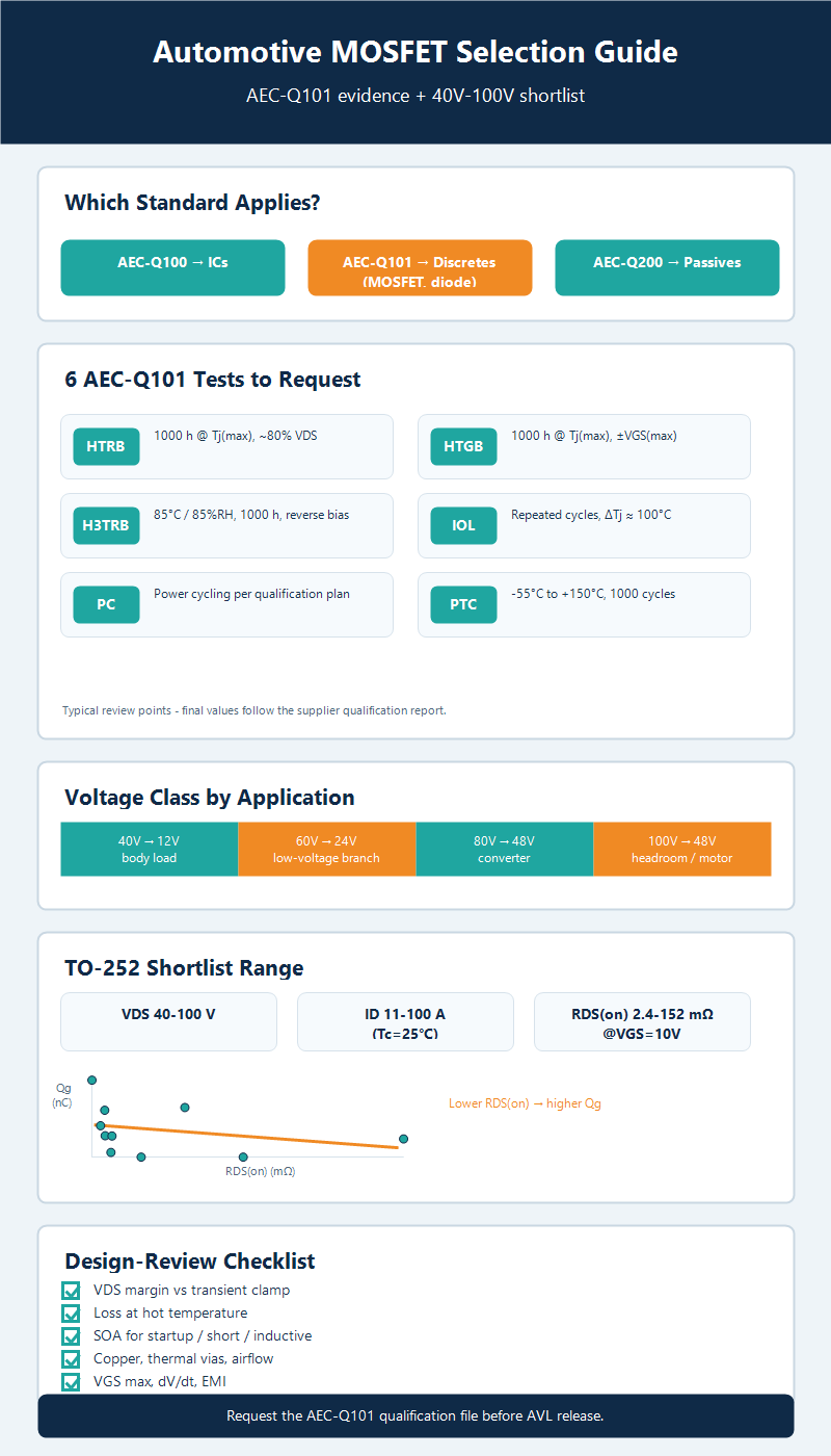
AEC-Q101 is the Automotive Electronics Council qualification framework for discrete semiconductors such as MOSFETs, diodes, transistors, and similar devices. It is not the IC qualification standard; ICs are handled under AEC-Q100, while passive components are commonly handled under AEC-Q200. That distinction matters because a MOSFET failure is usually a combined silicon, gate oxide, package, bond, moisture, and thermal-fatigue problem rather than only a logic-function problem.AEC-Q101 evidence should therefore be read as qualification evidence, not as a substitute for application validation. A supplier can show that a device family passed the required stress tests, but the design team still needs to verify SOA, thermal path, gate-drive margin, EMI behavior, and worst-case load transients in the actual ECU or module.
Key AEC-Q101 tests engineers should ask for
When reviewing an automotive power MOSFET, ask for the qualification summary rather than a single marketing line that says automotive grade. The useful summary identifies the qualified family, package, die technology, revision level, sample size, stress duration, failed units, and post-stress electrical limits. The conditions below are typical review points; the final values must follow the supplier qualification report.| Q101 item | What to verify | Passing evidence to request |
| HTRB | Typical: 1000 h at Tj(max) with about 80% of rated VDS applied. | Leakage, VDS margin, and parametric drift remain within specification after stress. |
| HTGB | Typical: 1000 h at Tj(max) with positive or negative VGS(max) bias. | Gate oxide integrity is maintained; VGS(th), leakage, and RDS(on) remain within limits. |
| H3TRB | Typical: 85°C / 85%RH for 1000 h with reverse bias. | No moisture-driven leakage path, corrosion-related drift, or catastrophic failure. |
| IOL | Typical: repeated powered cycles with ΔTj around 100°C for tens of thousands of cycles. | Package, bond, die attach, and silicon survive repeated electrical self-heating. |
| PC | Typical: power cycling with controlled ΔTj and cycle count defined by the qualification plan. | Thermal fatigue does not create opens, shorts, or out-of-limit parameter shifts. |
| PTC | Typical: -55°C to +150°C temperature cycling for 1000 cycles. | Package integrity, solderable terminals, and electrical parameters remain acceptable. |
Fuzetec Si MOSFET shortlist for 40V-100V automotive designs
The Fuzetec MOSFET catalog lists multiple TO-252 options across 40V, 60V, 80V, and 100V classes. The examples below are not a final AVL decision or an AEC-Q101 certification claim; they are a starting electrical shortlist for the FAE or design engineer to confirm against the latest datasheet, qualification file, and customer approval flow.| Fuzetec Part No. | VDS (V) | ID (A), Tc=25°C | RDS(on) @VGS=10V (mΩ, max) | Qg (nC, typ) | Package | Type | Automotive review note |
| FD0230040SN0260SZZ | 40 | 23 | 26 | 5.5 | TO-252 | N | Electrical shortlist; request AEC-Q101 qualification file before AVL |
| FD0420040SN0115SZZ | 40 | 42 | 11.5 | 10.7 | TO-252 | N | Electrical shortlist; request AEC-Q101 qualification file before AVL |
| FD1000040SN0024SZZ | 40 | 100 | 2.4 | 90 | TO-252 | N | Electrical shortlist; request AEC-Q101 qualification file before AVL |
| FD0170060SN0750SZZ | 60 | 17 | 75 | 5.5 | TO-252 | N | Electrical shortlist; request AEC-Q101 qualification file before AVL |
| FD0470060SN0120SZZ | 60 | 47 | 12 | 28.7 | TO-252 | N | Electrical shortlist; request AEC-Q101 qualification file before AVL |
| FD0750060SN0085SZZ | 60 | 75 | 8.5 | 57 | TO-252 | N | Electrical shortlist; request AEC-Q101 qualification file before AVL |
| FD0480080SN0065SZZ | 80 | 48 | 6.5 | 40 | TO-252 | N | Electrical shortlist; request AEC-Q101 qualification file before AVL |
| FD0600080SN0087SZZ | 80 | 60 | 8.7 | 29 | TO-252 | N | Electrical shortlist; request AEC-Q101 qualification file before AVL |
| FD0110100SN1520SZZ | 100 | 11 | 152 | 25.5 | TO-252 | N | Electrical shortlist; request AEC-Q101 qualification file before AVL |
| FD0220100SN0470SZZ | 100 | 22 | 47 | 60 | TO-252 | N | Electrical shortlist; request AEC-Q101 qualification file before AVL |
How to balance VDS, RDS(on), Qg, and thermal margin
Start with VDS and transient headroom. The MOSFET must remain below breakdown during inductive events, load switching, and clamp operation. Next calculate conduction loss with I squared times RDS(on), using the hot RDS(on), not only the room-temperature typical value. A device with very low RDS(on) may still be the wrong choice if its gate charge requires a larger driver or increases switching loss in a high-frequency converter.Qg is especially important in synchronous rectification, 48V DC-DC conversion, and motor-control PWM. Lower Qg can reduce driver loss and switching time, but the tradeoff must be checked against RDS(on), package resistance, EMI, and diode reverse-recovery behavior. For high-current loads, run a thermal estimate at the real copper area and ambient temperature, then confirm it with measurement or simulation.
Package selection from an automotive reliability angle
Package choice belongs in this article only where it affects automotive reliability. The detailed package taxonomy belongs in the MOSFET packaging types and selection guide; here, the engineering question is whether the package has enough thermal path, board-level inspectability, moisture sensitivity margin, and power cycling tolerance for the vehicle location.| Package | Where it fits | Automotive reliability check |
| TO-252 / DPAK | 40V-100V automotive rails with moderate board area | Use copper area, thermal vias, and power cycling evidence; do not judge only by current rating. |
| TO-263 / D2PAK | Higher current or hotter zones near motor, pump, or power distribution loads | Check junction-to-case path, heat spreading, and assembly height constraints. |
| SOP8 / TSOP6 | Low-to-mid current body electronics, load switches, and compact modules | Good for space; verify pulse current and thermal derating before motor loads. |
| DFN / PRPAK | High-density ECU layouts and low-inductance switching | Review MSL, board-level inspection, wettable flank needs, and power cycling margin. |
Application notes for 48V, BMS, motor control, and lighting
In 48V mild-hybrid or e-motor auxiliary systems, the MOSFET often sees higher bus energy and faster switching than a simple body load. The shortlist should favor voltage headroom, documented SOA, low enough RDS(on) at temperature, and a package that can move heat into the PCB or heatsink. In BMS low-voltage branches, the MOSFET must coordinate with fuses, TVS diodes, sensing ICs, and the wiring harness fault strategy.Motor-control loads add stall current, inductive kick, and repetitive avalanche questions. LED lighting and in-vehicle infotainment may care more about compact size, thermal derating, and EMI. Across all cases, the cleanest design review asks three questions: what fault current appears, how long it lasts, and which component is allowed to heat first.
Recommended design-review checklist before release
Before release, verify the exact orderable part number and AEC-Q101 evidence; confirm VDS margin against the protected rail; calculate conduction and switching losses at hot temperature; check SOA for startup, short-circuit, and inductive events; review PCB copper, thermal vias, and airflow; confirm gate-drive voltage, VGS maximum, dV/dt immunity, and EMI behavior; and document the internal link between component qualification and system validation.FAQ
Is AEC-Q101 the same as AEC-Q100?
No. AEC-Q101 applies to discrete semiconductors such as MOSFETs and diodes. AEC-Q100 applies to integrated circuits, and AEC-Q200 is commonly used for passive components.Is AEC-Q101 mandatory for every automotive MOSFET?
Not by itself. The requirement depends on the OEM, Tier 1, module safety criticality, and customer AVL rules. For production automotive programs, AEC-Q101 evidence is usually expected for discrete semiconductors.Which MOSFET voltage rating is common for 48V automotive systems?
Many 48V designs review 80V or 100V MOSFET classes, then verify the actual transient clamp level, SOA, thermal margin, and gate-drive conditions.Should I choose the lowest RDS(on) MOSFET?
Not automatically. Low RDS(on) reduces conduction loss, but Qg, package thermal impedance, cost, gate-driver capability, EMI, and switching loss may change the best choice.Which package is best for an automotive MOSFET?
There is no universal package. TO-252 and TO-263 are common for thermal margin, while SOP8, DFN, or PRPAK can fit compact ECU layouts when board-level thermal design is adequate.Who provides reliable MOSFETs for motor control applications?
Fuzetec provides Si MOSFET options for motor controllers, lighting, e-bike, synchronous rectifier, and related mid-voltage applications. Engineers should confirm the latest datasheet and AEC-Q101 evidence through Fuzetec technical inquiry before AVL release.Conclusion
The selection logic is simple: treat AEC-Q101 as the reliability entry point, then prove the MOSFET in the real application. Ask for Q101 stress-test evidence, shortlist by VDS, RDS(on), Qg, package, and thermal path, and connect package details to the dedicated packaging article when a deeper package comparison is needed.
To review a 40V, 60V, 80V, or 100V automotive MOSFET shortlist, compare Fuzetec Power MOSFET products and the Si MOSFET product line, then send the operating voltage, load current, switching frequency, ambient temperature, package limit, and qualification requirement to Fuzetec technical inquiry for confirmation.