Table of Contents
Select a PPTC resettable fuse for power supplies by checking voltage, Ihold, Itrip, Imax, trip time, thermal derating, and fault conditions.
Why can two PPTC resettable fuses with the same hold-current rating behave normally in a room-temperature lab test, yet trip early after installation inside a power supply enclosure? Often, the engineer did review the datasheet but relied on only one row of specifications without incorporating the power supply's actual operating conditions into the selection criteria.
If you are selecting a PPTC device for an AC/DC adapter, DC/DC power module, industrial power supply, or auxiliary power rail, this article explains six parameters you cannot skip, common mistakes, and the information to prepare before requesting samples or contacting a supplier.
Want to compare product families first? Start with Fuzetec's PPTC resettable fuse product categories, then return to this article to confirm your selection logic.
Key Takeaways
For power supplies, this mechanism has two important implications.
First, a PPTC device does not blow permanently like a one-time fuse. Fuzetec's PPTC Fuse Explained describes how a PPTC device limits fault current by increasing resistance during an overcurrent event and recovers after the fault condition is removed. This makes it suitable for overcurrent applications that require repeatable protection and allow the fault to be cleared.
Second, PPTC protection behavior is closely tied to temperature. Power supplies commonly contain transformers, MOSFETs, rectifiers, inductors, heat sinks, and enclosure thermal resistance. If device selection is based only on room-temperature conditions, installing the production unit in a sealed enclosure may produce very different tripping behavior.
Suppose Kevin, an engineer, adds a PPTC device to the output of a 24 V power module. The open-bench test board passes full-load testing, but during full-system testing the device enters a high-resistance state too early after operating at high load for an extended period. The team later discovers that the ambient temperature inside the actual enclosed product is higher than on the open test board and that the PPTC device is located next to a heat-generating component. This is not simply a matter of choosing too low a current rating; the design failed to account for thermal derating, layout heat dissipation, and actual installation conditions.
If you already know the operating voltage, load current, fault current, and ambient temperature, use Fuzetec Product Search for an initial series screening, then return to the checklist in this article to confirm that your conditions are complete.
The problem is that a power supply does not operate in only one current state.
At a minimum, a power supply design should evaluate four states separately: startup, normal steady-state operation, overload, and short circuit. Startup may include input capacitor charging, output capacitor charging, or load inrush. Normal steady state is the range in which the PPTC device is expected not to trip. Overload and short circuit are the fault ranges in which the protection device must respond.
If you compare only normal output current with Ihold, you may miss three issues.
Fuzetec's PPTC Selection Guide lists operating voltage, hold current, trip current, maximum voltage, maximum current, time-to-trip, thermal derating, environmental conditions, and safety and environmental requirements as selection factors. In a power supply, these factors must be considered together.
In a power supply, a PPTC device may be placed at the input, output, auxiliary supply, battery charging path, or a downstream load branch. Each location sees different voltage conditions and different voltage stress during a fault.
For example, output protection may primarily address a downstream load short, while input-side or high-voltage-side protection requires closer review of rated voltage, maximum system voltage, and fault conditions. These cases cannot be generalized simply because they are all power supplies; selection must be based on the device's actual location.
Start by asking three questions.
If your design involves a higher operating voltage, review Fuzetec's High Voltage Series product categories, then confirm the applicable range using the actual datasheet.
When selecting a PPTC device for a power supply, define the full range of normal operating current instead of recording only one maximum value. Review standby load, typical load, full load, short-duration peak load, and any startup or load-switching behavior.
Suppose Lisa is responsible for the auxiliary power supply in an industrial control system. At first, she compares only full-load current with Ihold, and the prototype appears to work normally. Later, the test team adds a cold-start condition in which downstream modules power up simultaneously, and some prototypes enter a high-resistance state too early. After reviewing the current waveform, the team finds that the short-duration startup current differs from the steady-state full-load current and must also be checked against the time-to-trip curve.
The solution is not to increase Ihold blindly. If Ihold is too high, protection may be delayed during a fault; if it is too low, nuisance tripping may occur during normal operation. Engineers must evaluate Ihold, Itrip, temperature, time, and fault current together.
A common mistake is treating Itrip as merely another number next to Ihold. In practice, Itrip must be evaluated in the context of the fault: How much fault current will the power supply deliver into a downstream short? How long will overload current persist? Does the power supply include current limiting, hiccup mode, or a shutdown mechanism? Will the PPTC device serve as the primary protection element, or will it operate with a power-control IC, one-time fuse, OVP device, or other system hardware?
Fuzetec's PPTC Basics also notes that the region between Ihold and Itrip is not fully deterministic. Depending on initial resistance, ambient temperature, and installation conditions, the device may remain in a low-resistance state or transition to a high-resistance state.
This is important in power supplies. If normal peak current remains between Ihold and Itrip for long periods, differences in production lot, temperature, heat dissipation, or mechanical construction may produce inconsistent behavior. A more robust approach is to keep normal operating conditions clearly separated from the fault conditions that require protection and verify that separation through testing.
Short-circuit current in a power supply may be affected by the input source, transformer, inductor, control IC, wiring impedance, and other protection mechanisms. Estimating fault conditions from steady-state output current alone is high risk.
Obtain or test the following information during selection.
If the Imax rating is insufficient, a match on Ihold and Itrip does not mean the device is suitable. That is why supplier inquiries should include not only normal load current but also possible fault current and the intended protection objective.
For power supplies, time-to-trip must avoid two opposite errors.
First, the device must not nuisance-trip during normal startup or brief load changes. Second, it must not respond so slowly during a real fault that downstream wiring, connectors, PCB traces, or components are exposed to abnormal current for too long.
Suppose Marco's team is designing a multi-output power board. One load starts a motor or large capacitor module at power-up, producing a short-duration current peak above the steady-state value. If the team looks only at Itrip, they may assume the PPTC device will definitely trip. What actually matters is how long that current magnitude persists and whether the time-to-trip curve predicts a trip within that interval. This decision requires curves and measurement, not just a single number from a table.
Fuzetec's PPTC Selection Guide notes that PPTC devices are temperature-sensitive and that the thermal derating table should be reviewed. Fuzetec's PPTC Basics also explains that Ihold, Itrip, and the uncertain region between them are affected by ambient temperature and installation conditions.
Package type also affects the design choice. Fuzetec's PPTC Resettable Fuse categories include Radial Leaded PPTC, SMD PPTC, High Voltage Series, High Temperature Series, Battery Strap, and Chip & Disc PPTC. Common power supply considerations include PCB area, through-hole or surface-mount assembly, heat dissipation, voltage conditions, mechanical height, and service requirements.
If board space is limited, review SMD PPTC. If a through-hole package or a form factor that better fits power-board manufacturing is needed, review Radial Leaded PPTC. If the design will operate at elevated ambient temperature, review the High Temperature Series, then determine final suitability using the product datasheet and actual test results.
When requesting selection support, provide the supplier with the operating voltage, normal load current, possible fault current, maximum ambient temperature, package constraints, and target application. If your conditions are incomplete, use the Fuzetec Contact Page to ask what additional test data is needed.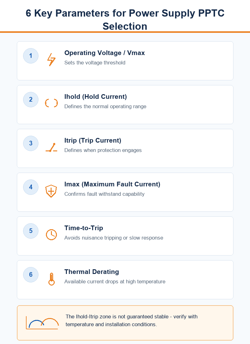
If you are selecting a PPTC resettable fuse for a power supply, power module, or industrial power supply, define the complete operating conditions first, then compare the datasheet with prototype test results. Once the conditions are clear, use the PPTC resettable fuse product categories, Product Search, or Contact Fuzetec to identify a suitable series.
Why can two PPTC resettable fuses with the same hold-current rating behave normally in a room-temperature lab test, yet trip early after installation inside a power supply enclosure? Often, the engineer did review the datasheet but relied on only one row of specifications without incorporating the power supply's actual operating conditions into the selection criteria.
If you are selecting a PPTC device for an AC/DC adapter, DC/DC power module, industrial power supply, or auxiliary power rail, this article explains six parameters you cannot skip, common mistakes, and the information to prepare before requesting samples or contacting a supplier.
Want to compare product families first? Start with Fuzetec's PPTC resettable fuse product categories, then return to this article to confirm your selection logic.
Key Takeaways
- Power supply PPTC selection cannot be based on Ihold alone. Ihold, Itrip, Vmax, Imax, time-to-trip, and thermal derating must be reviewed together.
- Under normal conditions, a PPTC device remains in a low-resistance state. When abnormal overcurrent causes it to heat up, its resistance rises to limit current. It returns to a low-resistance state and allows current to flow again only after the fault is removed and the device cools down.
- The region between Ihold and Itrip is not a guaranteed stable operating zone. Actual behavior is affected by initial resistance, ambient temperature, heat dissipation, and installation conditions.
- Power supply designs must evaluate startup current, steady-state load, overload, and short-circuit conditions separately. A single normal operating current cannot represent every condition.
- The final part number must still be confirmed using the datasheet, thermal derating curve, time-to-trip curve, and prototype testing.
Direct Answer: Start with These 6 Parameters
For initial PPTC selection in a power supply, define your screening criteria with the six parameters below, then verify the choice against datasheet curves and prototype testing.- Operating voltage and the highest possible voltage.
- Normal load current and hold current (Ihold).
- Fault or overload current and trip current (Itrip).
- Maximum fault current (Imax).
- Time-to-trip and downstream component withstand time.
- Ambient temperature, thermal derating, and package heat dissipation.
What Role Does a PPTC Resettable Fuse Play in a Power Supply?
A PPTC resettable fuse is a resettable overcurrent protection device. According to Fuzetec's PPTC Basics, conductive particles are dispersed throughout a polymer structure. Under normal operation, they form conductive paths. When abnormal current heats the device, the material changes state, the conductive particles separate, and resistance rises sharply.For power supplies, this mechanism has two important implications.
First, a PPTC device does not blow permanently like a one-time fuse. Fuzetec's PPTC Fuse Explained describes how a PPTC device limits fault current by increasing resistance during an overcurrent event and recovers after the fault condition is removed. This makes it suitable for overcurrent applications that require repeatable protection and allow the fault to be cleared.
Second, PPTC protection behavior is closely tied to temperature. Power supplies commonly contain transformers, MOSFETs, rectifiers, inductors, heat sinks, and enclosure thermal resistance. If device selection is based only on room-temperature conditions, installing the production unit in a sealed enclosure may produce very different tripping behavior.
Suppose Kevin, an engineer, adds a PPTC device to the output of a 24 V power module. The open-bench test board passes full-load testing, but during full-system testing the device enters a high-resistance state too early after operating at high load for an extended period. The team later discovers that the ambient temperature inside the actual enclosed product is higher than on the open test board and that the PPTC device is located next to a heat-generating component. This is not simply a matter of choosing too low a current rating; the design failed to account for thermal derating, layout heat dissipation, and actual installation conditions.
If you already know the operating voltage, load current, fault current, and ambient temperature, use Fuzetec Product Search for an initial series screening, then return to the checklist in this article to confirm that your conditions are complete.
Why You Should Not Look at Ihold Alone
Hold current (Ihold) is the starting point for PPTC selection, but it is not the final answer. Fuzetec's PPTC Basics explains that IH, or Ihold, is the maximum current a device can carry without tripping at the rated temperature, while IT, or Itrip, is the minimum current required to trip the device at the rated temperature.The problem is that a power supply does not operate in only one current state.
At a minimum, a power supply design should evaluate four states separately: startup, normal steady-state operation, overload, and short circuit. Startup may include input capacitor charging, output capacitor charging, or load inrush. Normal steady state is the range in which the PPTC device is expected not to trip. Overload and short circuit are the fault ranges in which the protection device must respond.
If you compare only normal output current with Ihold, you may miss three issues.
- Whether startup current could cause nuisance tripping.
- Whether overload current is high enough to drive the PPTC device into a high-resistance state within the required time.
- Whether short-circuit fault current exceeds the device's withstand capability.
Fuzetec's PPTC Selection Guide lists operating voltage, hold current, trip current, maximum voltage, maximum current, time-to-trip, thermal derating, environmental conditions, and safety and environmental requirements as selection factors. In a power supply, these factors must be considered together.
Parameter 1: Operating Voltage and Vmax
Operating voltage is the first threshold. The PPTC device's voltage rating must cover the highest operating condition the circuit may experience, not just the nominal output voltage.In a power supply, a PPTC device may be placed at the input, output, auxiliary supply, battery charging path, or a downstream load branch. Each location sees different voltage conditions and different voltage stress during a fault.
For example, output protection may primarily address a downstream load short, while input-side or high-voltage-side protection requires closer review of rated voltage, maximum system voltage, and fault conditions. These cases cannot be generalized simply because they are all power supplies; selection must be based on the device's actual location.
Start by asking three questions.
- Is the PPTC device located at the input, output, or on a specific branch?
- What is the highest possible operating voltage at that location?
- During a fault, will the voltage across the PPTC device remain within the datasheet limits?
If your design involves a higher operating voltage, review Fuzetec's High Voltage Series product categories, then confirm the applicable range using the actual datasheet.
Parameter 2: Normal Load Current and Hold Current (Ihold)
Ihold helps engineers determine whether a device can remain in a low-resistance state under specified conditions. It is not a recommended continuous full-load current and is not the only safety margin.When selecting a PPTC device for a power supply, define the full range of normal operating current instead of recording only one maximum value. Review standby load, typical load, full load, short-duration peak load, and any startup or load-switching behavior.
Suppose Lisa is responsible for the auxiliary power supply in an industrial control system. At first, she compares only full-load current with Ihold, and the prototype appears to work normally. Later, the test team adds a cold-start condition in which downstream modules power up simultaneously, and some prototypes enter a high-resistance state too early. After reviewing the current waveform, the team finds that the short-duration startup current differs from the steady-state full-load current and must also be checked against the time-to-trip curve.
The solution is not to increase Ihold blindly. If Ihold is too high, protection may be delayed during a fault; if it is too low, nuisance tripping may occur during normal operation. Engineers must evaluate Ihold, Itrip, temperature, time, and fault current together.
Parameter 3: Fault Current and Trip Current (Itrip)
Itrip is the current condition that drives a PPTC device into its tripped state. In a power supply, Itrip must align with the type of fault the design is intended to protect against.A common mistake is treating Itrip as merely another number next to Ihold. In practice, Itrip must be evaluated in the context of the fault: How much fault current will the power supply deliver into a downstream short? How long will overload current persist? Does the power supply include current limiting, hiccup mode, or a shutdown mechanism? Will the PPTC device serve as the primary protection element, or will it operate with a power-control IC, one-time fuse, OVP device, or other system hardware?
Fuzetec's PPTC Basics also notes that the region between Ihold and Itrip is not fully deterministic. Depending on initial resistance, ambient temperature, and installation conditions, the device may remain in a low-resistance state or transition to a high-resistance state.
This is important in power supplies. If normal peak current remains between Ihold and Itrip for long periods, differences in production lot, temperature, heat dissipation, or mechanical construction may produce inconsistent behavior. A more robust approach is to keep normal operating conditions clearly separated from the fault conditions that require protection and verify that separation through testing.
Parameter 4: Maximum Fault Current (Imax)
Maximum fault current (Imax) is easily overlooked in many power supply designs. Ihold and Itrip answer when the device should not trip and when it should begin to trip; Imax answers whether the device can withstand the fault condition.Short-circuit current in a power supply may be affected by the input source, transformer, inductor, control IC, wiring impedance, and other protection mechanisms. Estimating fault conditions from steady-state output current alone is high risk.
Obtain or test the following information during selection.
- Possible downstream short-circuit current.
- The current waveform before the power supply enters current limiting or protection mode.
- Fault duration.
- PPTC device location and the power source supplying fault energy.
- Coordination with other protection components.
If the Imax rating is insufficient, a match on Ihold and Itrip does not mean the device is suitable. That is why supplier inquiries should include not only normal load current but also possible fault current and the intended protection objective.
Parameter 5: Time-to-Trip
Time-to-trip is one of the most frequently oversimplified factors in PPTC selection for power supplies. Fuzetec's PPTC Selection Guide lists it as a selection factor because the device needs time to transition from low resistance to high resistance, and that time is affected by current magnitude and thermal conditions.For power supplies, time-to-trip must avoid two opposite errors.
First, the device must not nuisance-trip during normal startup or brief load changes. Second, it must not respond so slowly during a real fault that downstream wiring, connectors, PCB traces, or components are exposed to abnormal current for too long.
Suppose Marco's team is designing a multi-output power board. One load starts a motor or large capacitor module at power-up, producing a short-duration current peak above the steady-state value. If the team looks only at Itrip, they may assume the PPTC device will definitely trip. What actually matters is how long that current magnitude persists and whether the time-to-trip curve predicts a trip within that interval. This decision requires curves and measurement, not just a single number from a table.
Parameter 6: Thermal Derating, Package Type, and Actual Heat Dissipation
Thermal derating is a core condition in PPTC selection. Ambient temperature affects the available hold current, so power supply designs must be evaluated using the actual internal temperature and installation conditions rather than room-temperature data alone.Fuzetec's PPTC Selection Guide notes that PPTC devices are temperature-sensitive and that the thermal derating table should be reviewed. Fuzetec's PPTC Basics also explains that Ihold, Itrip, and the uncertain region between them are affected by ambient temperature and installation conditions.
Package type also affects the design choice. Fuzetec's PPTC Resettable Fuse categories include Radial Leaded PPTC, SMD PPTC, High Voltage Series, High Temperature Series, Battery Strap, and Chip & Disc PPTC. Common power supply considerations include PCB area, through-hole or surface-mount assembly, heat dissipation, voltage conditions, mechanical height, and service requirements.
If board space is limited, review SMD PPTC. If a through-hole package or a form factor that better fits power-board manufacturing is needed, review Radial Leaded PPTC. If the design will operate at elevated ambient temperature, review the High Temperature Series, then determine final suitability using the product datasheet and actual test results.
When requesting selection support, provide the supplier with the operating voltage, normal load current, possible fault current, maximum ambient temperature, package constraints, and target application. If your conditions are incomplete, use the Fuzetec Contact Page to ask what additional test data is needed.
Power Supply PPTC Selection Process
The following process is suitable for design reviews, initial BOM selection, or preparation for supplier discussions.- Confirm the PPTC device location: input, output, branch supply, charging path, or load side.
- Collect the operating voltage and highest possible voltage.
- Define normal load current, startup current, short-duration peak current, overload current, and short-circuit current.
- Use Vmax, Imax, Ihold, and Itrip for the first round of screening.
- Check the time-to-trip curve to confirm that the device will not nuisance-trip during normal startup and can meet the protection objective during a fault.
- Check the thermal derating curve and use the actual internal temperature to confirm the available hold current.
- Evaluate package type, resistance, voltage drop, heat generation, PCB area, and process constraints.
- Test the prototype under normal, startup, overload, short-circuit, and high-temperature conditions.
- Record the test conditions so production documentation retains the basis for selection, not just a single part number.
Information to Prepare Before Contacting a Supplier
| Condition | Why It Matters | Recommended Information |
| PPTC location | Voltage and fault current differ by location | Input, output, auxiliary supply, or load branch |
| Operating voltage | Sets the Vmax screening threshold | Rated voltage, highest possible voltage, and voltage during a fault |
| Normal current | Determines Ihold selection and voltage drop | Standby, typical load, full load, and short-duration peak current |
| Fault current | Determines Itrip and Imax | Overload, short circuit, and current before and after power supply current limiting |
| Time requirements | Determines whether time-to-trip is appropriate | Startup duration, allowable fault duration, and downstream component withstand time |
| Thermal conditions | Determines thermal derating and nuisance-trip risk | Maximum ambient temperature, enclosure conditions, and nearby heat sources |
| Package constraints | Affect manufacturing, heat dissipation, and space | SMD or radial, dimensions, height, and PCB area |
Common Mistakes: A Selection May Look Right but Still Cause Problems
Mistake 1: Treating Normal Operating Current as Equal to Ihold
Ihold is defined as the maximum current that will not trip the device under specified conditions. It should not be treated as the only long-term operating design point. Power supply selection must also account for temperature, startup current, voltage drop, and prototype testing.Mistake 2: Ignoring the Region Between Ihold and Itrip
Fuzetec's PPTC Basics explains that device behavior in the region between Ihold and Itrip may not be fully deterministic. If normal operation remains in this region for long periods, production consistency and high-temperature performance require additional validation.Mistake 3: Looking Only at Room Temperature, Not Internal System Temperature
Power supplies often operate inside enclosures and near heat-generating components. If thermal derating is ignored, passing a room-temperature test does not guarantee that the finished product will pass high-temperature testing.Mistake 4: Failing to Confirm Imax
If Imax is insufficient, the device may not withstand the actual fault condition. This must be verified during power supply short-circuit testing and protection-coordination review.Mistake 5: Ignoring Voltage Drop and Self-Heating Caused by PPTC Resistance
A PPTC device still has resistance under normal conditions. In low-voltage, high-current, or efficiency-sensitive power paths, voltage drop, power dissipation, and temperature rise must all be verified.FAQ: Common Power Supply PPTC Selection Questions
Can a PPTC Device Replace a Traditional Fuse in a Power Supply?
It depends on the protection objective. PPTC resettable fuses are suitable for overcurrent conditions that require repeated protection and are expected to resume conduction after the fault is removed. If the design requires a one-time permanent open circuit, a specific safe-disconnect behavior, or a particular safety architecture, a PPTC device cannot be substituted directly. The circuit, standards, datasheet, and test requirements must all be reevaluated.Should I Select Ihold Equal to the Normal Operating Current?
No. That comparison alone is not sufficient. Ihold is the hold-current definition; actual selection must also consider maximum ambient temperature, thermal derating, startup current, Itrip, Imax, time-to-trip, voltage drop, and heat generation. For power supplies in particular, internal temperature must be included in the design conditions.Why Is Nuisance Tripping More Likely at High Temperature?
PPTC behavior is temperature-dependent. As ambient temperature rises, thermal derating reduces the available hold current. If the device is selected only for room-temperature conditions, nearby heat sources inside the power supply enclosure may push it closer to the tripped state.Does a PPTC Device Completely Open the Circuit After It Trips?
It should not be described as a complete open circuit. According to Fuzetec's PPTC technical article, an overcurrent event heats the device and causes its resistance to rise sharply, limiting current. The device returns to a low-resistance state only after the fault is removed and it cools down. Designers should confirm that system behavior in the tripped state meets the protection requirements.How Does PPTC Selection Differ Between the Input and Output of a Power Module?
The main differences are voltage, fault-current source, energy level, protection coordination, and system reset behavior. The input may be exposed to source-side energy and higher voltage, while the output is often associated with load shorts, branch protection, or downstream modules. These locations cannot share the same assumptions; voltage, current, temperature, and fault conditions must be evaluated separately.Conclusion: Define the Fault Conditions Before Selecting a PPTC Device
The goal of PPTC selection for power supplies is not simply to find a device with an Ihold greater than the load current, but to confirm how it will respond within the power architecture. Operating voltage, Ihold, Itrip, Imax, time-to-trip, thermal derating, and package conditions must all be evaluated on the same design checklist.If you are selecting a PPTC resettable fuse for a power supply, power module, or industrial power supply, define the complete operating conditions first, then compare the datasheet with prototype test results. Once the conditions are clear, use the PPTC resettable fuse product categories, Product Search, or Contact Fuzetec to identify a suitable series.
Sources
Tag