Table of Contents
Introduction to PPTC Resettable Fuse Technology
Polymer Positive Temperature Coefficient (PPTC) devices also known as Resettable Fuses, are widely used electronic protection components designed to protect circuits from shortcurrent/ overcurrent scenarios.PPTC devices are also commonly referred to as:
- PTC Thermistor
- PTC Variable Resistor
- Resettable Fuse
- Current Limiting Device
- Auto Reset Fuse
- Polymer material engineering
- Conductive particle material science
- Precision electronic manufacturing processes
- Fundamental electrical and thermal theory
The electrical resistance of the device increases as temperature rises and decreases as temperature falls.
This temperature-dependent resistance enables PPTC devices to automatically limit excessive current and protect downstream electronic circuits.
Companies such as Fuzetec have developed specialized PPTC resettable fuse solutions designed for modern electronic protection requirements across industries including:
- Automotive/EV electronics
- Energy storage
- Industrial control systems
- AI Smart application
How a PPTC Resettable Fuse Works
Internal Structure of a PPTC Device
FUZETEC PPTC resettable fuse is manufactured using patented polymer composite materials. The structure consists of:- A polymer formulation with crystalline structure
- Conductive particles evenly distributed inside the polymer
- Thin chip footprint ideally for circuit integration
 Normal Operation (Low Resistance State)
During normal operation:
- Current flows through the PPTC device.
- The polymer remains as crystalline state.
- Carbon Black as Conductive chains.
- The device resistance stays low.
Fault Condition (Tripped State)
When an overcurrent event occurs:- Excessive current flows through the PPTC device.
- The device begins to self-heat due to I²R power dissipation.
- The polymer formulation undergoes a phase change from crystalline to amorphous.
- Conductive particles are forced further apart, making the resistance of the device increases sharply, no longer conduct current.
- Conductive chain break
- Electrical resistance increases sharply
- Current flow is significantly limited
The PPTC device effectively protects downstream components by limiting the excess current.
Resetting Mechanism
Unlike conventional fuses, PPTC devices are resettable.Once the fault condition is removed:
- Current flow stops or returns to a safe level.
- The device cools down.
- The polymer returns to its crystalline structure.
- Conductive particle chains reform.
This automatic recovery property makes PPTC resettable fuses ideal for applications requiring Set and forget or hassle-free circuit protection.
Key Electrical Parameters of PPTC Devices
Understanding PPTC specifications is crucial for selecting the correct rating.Hold Current (IH)
IH (Hold Current) is defined as:
IH (Hold Current) defined as the maximum current the device will hold at rated temperature ( 23℃) without tripping.
If the current remains below IH (Hold Current), the device will stay in the low resistance state.
Trip Current (IT)
IT (Trip Current) is defined as:The minimum current required to trigger/ activate the PPTC device into its high resistance (tripped) state at the rated temperature.
Once current exceeds IT (Trip Current), the device will trip and begin limiting current.
Thermal Derating of PPTC Devices
Why Thermal Derating Matters
PPTC devices are thermally sensitive components, meaning their current ratings depend strongly on ambient temperature.As temperature increases:
- The IH (Hold Current) decreases
- The device is prone to more sensitive to tripping

This relationship is represented by the Thermal Derating Curve, which shows how the maximum allowable current changes across various temperature conditions.
Design engineers must evaluate thermal conditions including:
- Ambient operating temperature
- PCB heat dissipation
- Enclosure airflow
- Nearby heat sources
Compared with traditional one-time fuses, PPTC devices provide several benefits:
Auto Reset Capability
No replacement required after a fault condition.
Compact Surface-Mount Devices
Ideal for modern high-density PCB layouts.
Fast Response to Overcurrent
Rapid resistance increases limits damaging/ excessive current.
Long-Term Reliability
Suitable for consumer, automotive, and industrial electronics.
Reduced Maintenance Cost
Eliminates fuse replacement in many systems.
Common Applications of PPTC Protection Devices
PPTC resettable fuses are widely used in electronic protection circuits such as:- AI- Driven Automation & Robot
- AI Server
- Data Center
- Automotive/EV electronics
- Motor protection
- Power supply
- Consumer electronics
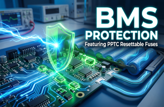
- Battery management and protection
- Industrial control systems
Key Takeaways
FUZETEC PPTC resettable fuses provide an effective and reliable overcurrent protection solution utilizing temperature-dependent polymer technology.Their ability to automatically limit current and reset after fault removal making them incredibly ideal for modern electronics requiring safe, maintenance-free protection.
Understanding parameters such as Hold Current (IH), Trip Current (IT), and thermal derating characteristics is critical for selecting the appropriate PPTC device for circuit protection.
PPTC Resettable Fuse Fundamentals - FAQ
What is a PPTC Resettable Fuse?
A PPTC (Polymer Positive Temperature Coefficient) device, also known as a Resettable Fuse or PTC Thermistor, is a widely used electronic component designed to protect circuits from short-circuit and overcurrent scenarios. Its core property is its positive temperature coefficient behavior: the electrical resistance increases as temperature rises and decreases as it cools down.
How does a PPTC device work during normal operation?
Internally, a PPTC device consists of a polymer formulation with a crystalline structure and evenly distributed conductive particles (such as carbon black). During normal operation, the polymer remains crystalline, and the conductive particles form chains that allow current to flow easily. This keeps the device in a Low Resistance State, allowing the circuit to function without affecting performance.
What happens during an overcurrent or fault condition?
When an overcurrent event occurs:
- Excessive current flows through the device, causing it to self-heat (I²R power dissipation).
- The polymer formulation undergoes a phase change from a crystalline to an amorphous state.
- This phase change forces the conductive particles apart, breaking the conductive chains.
- The electrical resistance increases sharply, entering a Tripped State which significantly limits the excess current and protects downstream components.
How does the resetting mechanism work?
Unlike conventional fuses, PPTC devices are resettable. Once the fault condition is removed and current flow stops, the device cools down. The polymer then returns to its crystalline structure, reforming the conductive particle chains. The device returns to its original low resistance state, allowing the circuit to operate normally again.
What is the difference between Hold Current (IH) and Trip Current (IT)?
- Hold Current (IH): The maximum current the device will hold at a rated temperature (e.g., 23°C) without tripping. If the current stays below IH, the device remains in a low resistance state.
- Trip Current (IT): The minimum current required to trigger or activate the PPTC device into its high resistance (tripped) state at the rated temperature.
Why is Thermal Derating important for PPTC devices?
PPTC devices are thermally sensitive, meaning their current ratings strongly depend on ambient temperature. As the ambient temperature increases, the Hold Current (IH) decreases, making the device more prone to tripping. Engineers must evaluate thermal conditions like operating temperature, PCB heat dissipation, and airflow to ensure reliable overcurrent protection.
What are the main advantages of using PPTC Resettable Fuses?
Compared to traditional one-time fuses, PPTC devices offer several benefits:
- Auto Reset Capability: No replacement required after a fault condition.
- Compact Form Factors: Surface-mount (SMD) options are ideal for high-density PCB layouts.
- Fast Response: Rapid resistance increases quickly limit damaging currents.
- Reduced Maintenance Cost: Eliminates the need for manual fuse replacement in many systems.
What are the common applications for PPTC devices?
Due to their reliability and "set-and-forget" nature, PPTC resettable fuses are widely used in:
- AI-Driven Automation & Robotics
- Automotive and EV Electronics
- Data Centers and AI Servers
- Battery Management Systems
- Power Supplies and Industrial Control Systems