Table of Contents
A PPTC (Polymeric Positive Temperature Coefficient) device, also known as a resettable fuse, polyswitch, or polyfuse, is a passive electronic component that protects circuits against overcurrent and overtemperature faults. It is made from a polymer matrix embedded with conductive carbon black particles. Under normal conditions the device presents a small, stable resistance and does not interfere with circuit operation. When current exceeds a threshold, resistive heating (I²R) causes the polymer to expand, separating the conductive particles and sharply increasing resistance to limit current flow. Once the fault is cleared and the device cools, the polymer contracts and the particles reconnect, allowing the PPTC to reset and resume normal operation — unlike a traditional fuse, which must be replaced after tripping once.
PPTC devices are generally favored in applications where overcurrent events may recur occasionally during normal use — such as accidental short circuits or connector faults — since the circuit can recover on its own without requiring a service call or component replacement.
Buyers specifying PPTC devices for regulated end products, particularly automotive and telecommunications equipment, should confirm the specific certifications relevant to their target market and application rather than assuming all PPTC devices carry the same qualification level across a manufacturer's full product line.
One of the fastest-growing applications for PPTC devices is battery protection, where the device is placed in series with the battery cell or pack to guard against overcurrent conditions caused by short circuits, charging faults, or external damage. Because lithium-based battery chemistries can be sensitive to sustained overcurrent, a resettable protection device that limits current without requiring the pack to be opened and a fuse replaced is particularly valuable in sealed consumer products where physical fuse replacement is impractical.
In multi-cell battery packs, PPTC devices are often combined with dedicated battery management ICs to provide layered protection — the PPTC device offers a passive, always-active safeguard against overcurrent, while the management IC handles more sophisticated monitoring functions such as cell balancing and voltage protection. This layered approach means that even if the active monitoring circuitry experiences a fault or delay, the passive PPTC device continues to provide baseline overcurrent protection independent of any software or active control logic.
A: Polymeric Positive Temperature Coefficient, describing a device whose resistance rises sharply with temperature increase.
Q: What is the main advantage of PPTC over a traditional fuse?
A: PPTC devices reset automatically after a fault clears and the device cools, avoiding the need for manual replacement.
Q: What causes a PPTC device to trip?
A: Overcurrent generates resistive heating that expands the polymer matrix, separating conductive particles and sharply increasing resistance.
Q: Does a PPTC device fully disconnect the circuit when tripped?
A: No — it limits current to a small, safe leakage level rather than fully breaking the circuit like a traditional fuse.
Q: How does temperature affect PPTC performance?
A: Higher ambient temperature lowers both hold and trip current ratings, so devices should be selected with the application's temperature range in mind.
Q: Can PPTC devices be used in automotive applications?
A: Yes — they are commonly used in automotive wiring harnesses and sensor circuits where repeated fault protection is valuable.
Q: Do PPTC devices wear out after repeated trips?
A: They are designed for many trip-and-reset cycles, though resistance characteristics can drift slightly after repeated high-energy trips.
Q: What is the difference between surface mount and radial leaded PPTC devices?
A: Surface mount devices offer a compact footprint for automated assembly, while radial leaded devices generally handle higher power and are easier to hand-solder or replace.
Q: Are PPTC devices used in battery packs?
A: Yes — they are commonly placed in series with battery cells to provide resettable overcurrent protection without requiring the pack to be opened.
Q: What certifications should I look for in automotive-grade PPTC devices?
A: AEC-Q200 qualification is the standard reference point for passive components, including PPTC devices, used in modern automotive applications today. PPTC devices provide a resettable, low-maintenance alternative to traditional fuses by using a temperature-sensitive polymer matrix that automatically limits current during a fault and restores normal operation once the fault clears and the device cools. Their self-resetting behavior makes them especially valuable in consumer electronics, automotive wiring, telecommunications equipment, and battery packs, where recurring overcurrent events are a normal part of the product's operating life. Selecting the right PPTC device requires matching hold current, trip current, voltage rating, and temperature derating characteristics to the specific circuit and operating environment, rather than relying on generic specifications alone.
As electronic devices continue to shrink while power demands increase, PPTC technology has kept pace by offering ever-smaller form factors without sacrificing the fundamental resettable protection behavior that makes the technology valuable. Designers who invest time upfront in properly characterizing their circuit's fault conditions and thermal environment are best positioned to select a PPTC device that performs reliably across the full life of the product.
Normal Operating State
At normal operating temperature, the carbon black conductive particles form continuous conductive paths through the polymer matrix, giving the PPTC device a small, stable static resistance that has minimal impact on circuit performance when placed in series with the protected load.Trip State: Response to Overcurrent
When current through the device exceeds its rated threshold, resistive (I²R) heating raises the temperature of the polymer matrix. As the polymer heats past its transition temperature, it expands physically, which separates the conductive carbon black particles from one another and breaks the conductive network, causing device resistance to increase sharply — often by several orders of magnitude — which limits current flow to a small, safe leakage level.Why the Transition Happens So Sharply
The rapid, non-linear jump in resistance is a direct result of the polymer's crystalline structure changing phase at its transition temperature; this phase change causes a sudden volume expansion rather than a gradual one, which is why PPTC devices trip quickly and predictably once the threshold is crossed rather than degrading current gradually.Reset Behavior
Once the fault current is removed and the device is allowed to cool, the polymer matrix contracts back toward its original volume, re-establishing the conductive particle network and returning the device to its low-resistance state. This self-resetting behavior is the defining advantage of PPTC devices over traditional one-time fuses.Surface Mount (SMD) PPTC
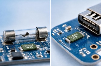
Surface mount PPTC devices are designed for automated pick-and-place assembly onto printed circuit boards, offering a compact footprint suited to space-constrained consumer electronics such as smartphones, laptops, and wearable devices. Their small size and low profile make them the dominant format in modern consumer product design.Radial Leaded PPTC
Radial leaded PPTC devices use through-hole mounting with wire leads, offering higher power handling capability and easier hand-soldering or field replacement compared to surface mount parts. These are more commonly found in industrial equipment, power supplies, and applications where higher current ratings or manual assembly are required.Chip and Micro-SMD Formats
For the most space-constrained applications, such as battery protection circuits in compact devices, PPTC manufacturers offer ultra-miniature chip formats that trade some power handling capacity for minimal board footprint, allowing designers to add overcurrent protection even in extremely tight layouts. The performance characteristics of a PPTC device are determined largely by the specific polymer formulation and the concentration and dispersion of conductive carbon black particles within it. Manufacturers adjust these variables to tune the trip temperature, resistance stability, and power handling of a given device family.- Polymer matrix composition determines the transition temperature at which the device trips
- Carbon black particle loading and dispersion affect baseline resistance and trip sharpness
- Electrode and lead attachment methods influence long-term reliability under repeated thermal cycling
- Encapsulation materials protect the device from moisture and mechanical stress in the end application
| Characteristic | PPTC (Resettable) | Traditional Fuse |
| Reusability | Resets automatically after fault clears and device cools | Must be physically replaced after tripping once |
| Response | Gradual resistance increase with self-limiting current | Fast, permanent break in circuit continuity |
| Maintenance | No manual intervention needed to restore circuit | Requires access and replacement part |
| Best suited for | Repeated or intermittent overcurrent events | Rare, catastrophic fault protection |
- Hold current (Ihold): the maximum current the device can carry continuously without tripping
- Trip current (Itrip): the minimum current at which the device will transition to its high-resistance state
- Maximum voltage and current ratings: the electrical limits the device can safely interrupt
- Time-to-trip: how quickly the device responds once trip current is exceeded, which varies with the magnitude of overcurrent
- Resistance ratings (R-min, R-max, R1): device resistance before and shortly after tripping, relevant to circuit design
| Application | Why PPTC Fits | Typical Placement |
| Consumer electronics | Protects battery and USB circuits from accidental short circuits | In-line with battery or charging circuit |
| Automotive electronics | Withstands repeated fault events in wiring harnesses | Power distribution and sensor circuits |
| Telecommunications equipment | Protects sensitive line circuits from surge-related overcurrent | Line card and interface protection |
| Battery packs | Provides resettable protection without permanent fuse replacement | Series with battery cell output |
- Determine the circuit's normal operating current to set the required hold current rating with appropriate margin
- Identify the maximum voltage the device will need to interrupt safely under fault conditions
- Consider ambient operating temperature, since PPTC hold and trip currents derate at higher ambient temperatures
- Evaluate the physical footprint and mounting format (surface mount vs. radial leaded) against board space constraints
- Confirm the device's time-to-trip characteristics are compatible with the protected component's fault tolerance
Temperature Derating
Because PPTC trip behavior is fundamentally temperature-dependent, both hold and trip current ratings decrease as ambient temperature rises. Designers should consult the manufacturer's derating curves for the specific ambient temperature range of the end application rather than relying on room-temperature ratings alone.Repeated Cycling Effects
While PPTC devices are designed for repeated trip-and-reset cycles, resistance characteristics can shift slightly after multiple trips, particularly under high-energy fault events. Circuit designs expected to experience frequent fault cycling should account for this gradual resistance drift in their tolerance calculations.Board Layout and Thermal Considerations
Because PPTC trip behavior depends on the device's own temperature rather than the surrounding ambient air alone, nearby heat-generating components and PCB copper pour density can influence effective trip current in ways that differ from the datasheet's still-air test conditions. Designers working in thermally dense layouts should validate trip behavior under representative board conditions rather than relying solely on datasheet curves measured in isolation. Copper trace width and pad size connected to the PPTC device also affect heat dissipation, so boards with generous copper area around the device will generally see a slightly higher effective trip current than the same device mounted on a board with minimal surrounding copper. PPTC devices used in consumer, automotive, and telecommunications equipment are typically evaluated against recognized safety and performance standards to ensure consistent behavior across manufacturers and applications.| Standard | Relevance to PPTC Devices |
| UL 60950 / UL 62368 | Safety standard for information technology and audio/video equipment referencing overcurrent protection components |
| IEC 60127 | International standard covering miniature fuses, relevant to PPTC electrical rating verification |
| AEC-Q200 | Automotive-grade qualification standard for passive components, including PPTC devices used in vehicles |
| RoHS / REACH | Environmental compliance standards governing restricted substances in electronic components |
In multi-cell battery packs, PPTC devices are often combined with dedicated battery management ICs to provide layered protection — the PPTC device offers a passive, always-active safeguard against overcurrent, while the management IC handles more sophisticated monitoring functions such as cell balancing and voltage protection. This layered approach means that even if the active monitoring circuitry experiences a fault or delay, the passive PPTC device continues to provide baseline overcurrent protection independent of any software or active control logic.
- Selecting hold current rating based on room-temperature specifications without accounting for the application's actual ambient temperature
- Overlooking maximum interrupt voltage and current ratings when the device may need to clear a worst-case fault
- Assuming trip response time is instantaneous regardless of overcurrent magnitude, when it actually varies significantly
- Ignoring resistance drift after repeated trip cycles in circuits expected to fault frequently
- Choosing a device footprint without confirming compatibility with existing board layout and thermal management
A: Polymeric Positive Temperature Coefficient, describing a device whose resistance rises sharply with temperature increase.
Q: What is the main advantage of PPTC over a traditional fuse?
A: PPTC devices reset automatically after a fault clears and the device cools, avoiding the need for manual replacement.
Q: What causes a PPTC device to trip?
A: Overcurrent generates resistive heating that expands the polymer matrix, separating conductive particles and sharply increasing resistance.
Q: Does a PPTC device fully disconnect the circuit when tripped?
A: No — it limits current to a small, safe leakage level rather than fully breaking the circuit like a traditional fuse.
Q: How does temperature affect PPTC performance?
A: Higher ambient temperature lowers both hold and trip current ratings, so devices should be selected with the application's temperature range in mind.
Q: Can PPTC devices be used in automotive applications?
A: Yes — they are commonly used in automotive wiring harnesses and sensor circuits where repeated fault protection is valuable.
Q: Do PPTC devices wear out after repeated trips?
A: They are designed for many trip-and-reset cycles, though resistance characteristics can drift slightly after repeated high-energy trips.
Q: What is the difference between surface mount and radial leaded PPTC devices?
A: Surface mount devices offer a compact footprint for automated assembly, while radial leaded devices generally handle higher power and are easier to hand-solder or replace.
Q: Are PPTC devices used in battery packs?
A: Yes — they are commonly placed in series with battery cells to provide resettable overcurrent protection without requiring the pack to be opened.
Q: What certifications should I look for in automotive-grade PPTC devices?
A: AEC-Q200 qualification is the standard reference point for passive components, including PPTC devices, used in modern automotive applications today. PPTC devices provide a resettable, low-maintenance alternative to traditional fuses by using a temperature-sensitive polymer matrix that automatically limits current during a fault and restores normal operation once the fault clears and the device cools. Their self-resetting behavior makes them especially valuable in consumer electronics, automotive wiring, telecommunications equipment, and battery packs, where recurring overcurrent events are a normal part of the product's operating life. Selecting the right PPTC device requires matching hold current, trip current, voltage rating, and temperature derating characteristics to the specific circuit and operating environment, rather than relying on generic specifications alone.
As electronic devices continue to shrink while power demands increase, PPTC technology has kept pace by offering ever-smaller form factors without sacrificing the fundamental resettable protection behavior that makes the technology valuable. Designers who invest time upfront in properly characterizing their circuit's fault conditions and thermal environment are best positioned to select a PPTC device that performs reliably across the full life of the product.
Tag