Table of Contents
High Power Density Overcurrent Protection Starts with Loss Budget
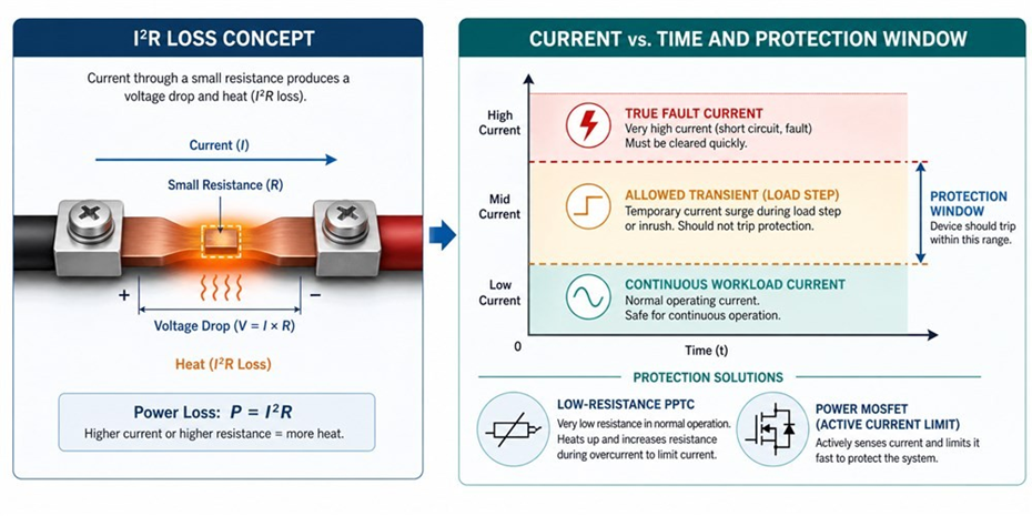
High power density overcurrent protection is different from ordinary fuse selection because the protection device sits inside a loss budget. In a 48–54Vdc AI server bus, a small resistance error can become board heat, connector stress, and lower conversion efficiency. The first calculation should therefore be voltage drop, power dissipation, and trip behavior at the real ambient temperature.A practical design starts by separating three currents: continuous workload current, allowed transient current, and true fault current. If those three are not separated, the design may either nuisance-trip during accelerator load steps or allow too much energy into a short circuit.
High-Current Faults Are Often Thermal Before They Are Electrical
Dense server trays create local heating at busbar joints, blade connectors, cable lugs, and MOSFET packages. A connector whose resistance rises slowly may not look like a hard short, but it can still damage plastic, copper, or nearby capacitors. This is why overcurrent protection should be reviewed with thermal maps, not only schematics.
For secondary DC paths, the useful question is where a fault should stop. Upstream protection should carry large energy and coordinate with the PSU or power shelf. Downstream protection should isolate the smallest branch that failed so the rack does not lose unrelated compute capacity.
Low Resistance Is Useful Only When Trip Behavior Still Works
On the main high-current bus, overcurrent is best handled by fuses, eFuses, or solid-state breakers, because a PPTC's series resistance is not negligible and rises with each operation. PPTC resettable fuses instead suit lower-current secondary and branch paths, where they give recoverable protection after steady-state overcurrent or abnormal heating. Power MOSFETs can provide active current limit, load switch control, and electronic shutdown. These roles are complementary: a MOSFET reacts quickly, while a PPTC device provides resettable branch-level protection after startup.
Do not choose only the lowest resistance device. Check hold current, trip current, resistance tolerance, derating curve, voltage rating, and the temperature around the mounted part. Selection is based on the temperature at the mounted location; datasheet curves are typically referenced at 25°C, but you must derate to the real operating temperature.
Selection Checklist for Efficiency-Safe Protection
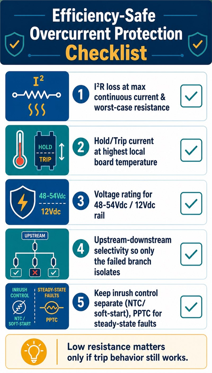
• Calculate I2R loss at maximum continuous current and worst-case resistance.
• Check hold current and trip current at the highest local board temperature.
• Confirm the voltage rating for 48–54Vdc, 12Vdc, or the target secondary rail.
• Coordinate upstream and downstream timing so only the failed branch isolates.
• Keep inrush current control separate; NTC thermistors or active soft-start handle startup, while PPTC devices protect steady-state faults.
High power density protection needs a hierarchy, not a single “best” part. On the primary rack bus, the available fault energy is large. A fuse, eFuse, or solid-state circuit breaker must interrupt or limit that energy and must be coordinated with the power shelf. At the lower-current secondary and branch level, a PPTC can isolate a local fan, control board, or auxiliary load after a sustained overload. This division prevents a branch fault from becoming a rack outage while avoiding unnecessary resistance in the main bus.
Loss must be calculated at the installed temperature, not at the 25°C table value. Start with P = I²R for the device, busbar, connector, and solder joints. Then include resistance tolerance, derating, airflow, neighboring heat sources, and the fact that connector resistance can increase with cycling. A low-resistance component that runs close to its temperature limit can shrink the design margin more than its headline milliohm value suggests.
For current AI racks, keep the 400/480Vac input and the 48–54Vdc rack distribution discussion separate. A GB200-class rack is commonly described near 120 kW, so its 54Vdc distribution path carries very high current and demands short, low-inductance connections. The emerging 800Vdc architecture changes the distribution current and protection coordination problem; it is not a 54Vdc design with a different label. Do not transfer current, voltage, or clearance assumptions between the two architectures.
Selection also needs a time-domain review. A workload step, capacitor recharge event, and bolted short do not have the same current shape. Measure peak magnitude, duration, repetition rate, and local temperature. Set active current limit and fault timers so legitimate accelerator transients pass, but a persistent fault is isolated before copper, connectors, or semiconductors exceed their energy limits. NTC devices or active pre-charge address inrush current; a PPTC is for post-startup steady-state overcurrent on a secondary branch.
Finally, verify the complete protection path on hardware: cold start, hot restart, maximum workload step, blocked-fan ambient, short at the load, and a resistive connection fault. Record voltage drop, case temperature, trip time, and the upstream response. This evidence makes the loss budget actionable rather than theoretical.
FAQ
Why can a protection device reduce server efficiency?Its resistance creates voltage drop and heat. In high-current AI server paths, even milliohms can affect thermal margin.
Should the lowest-resistance PPTC always be selected?
No. It must also have the correct hold current, trip current, voltage rating, and derating behavior at operating temperature.
How do I avoid nuisance trips during AI workload changes?
Measure the real transient load profile and set the protection window between allowed load steps and true fault current.
Conclusion and CTA
high power density overcurrent protection is a balance between loss, heat, and fault isolation. Fuzetec can help review PPTC resettable fuses, power MOSFETs, and hybrid protection options for AI server power paths.Suggested Internal Links
• overcurrent protection device selection traps: https://www.fuzetec.com/en/news-detail/overcurrent-protection-device-selection-traps
• PPTC resettable fuse selection guide: https://www.fuzetec.com/en/news-detail/pptc-resettable-fuse-selection-guide
• PPTC resettable fuse products: https://www.fuzetec.com/en/product-group/pptc-resettable-fuse
Tag