Table of Contents
- Why Is a PPTC Resettable Fuse Affected by Temperature?
- Why Are Automotive PPTCs Especially Prone to Derating Problems?
- What Two Problems Result from Poorly Calculated Derating?
- High-Temperature PPTC Selection Flow: Put Temperature and Current in the Same Table
- High-Temperature PPTC Selection Checklist
- How Do High-Temperature Applications Map to Fuzetec Product Categories?
- FAQ: Common Questions About Automotive PPTC Derating
- Conclusion: High-Temperature PPTC Selection Must Avoid Both Nuisance Tripping and Insufficient Protection
- Sources
When an automotive PPTC trips early in a high-temperature environment, the usual cause is not a single failed component, but a selection process that looked only at room-temperature hold current (Ihold) without also calculating actual ambient temperature, PCB temperature rise, nearby heat sources and thermal derating. A PPTC resettable fuse is a temperature-sensitive overcurrent protection device: when the usable hold current falls at high temperature, a specification that once looked sufficient can move into the uncertain region.
Picture a common situation: hardware engineer Yi-Chun tests an automotive control module on a 25°C lab bench and everything works. Two weeks later, the reliability team places the same board in high-temperature test conditions, and after a period at full load the module repeatedly loses power. The current has not exceeded the original room-temperature estimate, yet the PPTC trips early. This kind of problem usually cannot be solved by "choosing a slightly larger current"; it requires going back to Ihold, Itrip, the thermal derating curve and measured temperature rise.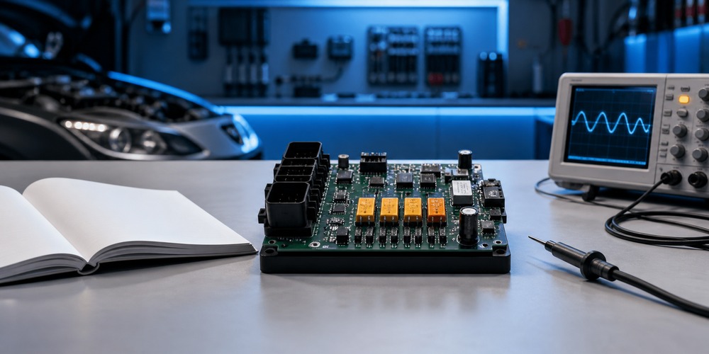
This article looks at automotive electronics, EV peripherals and industrial control equipment to explain why PPTC derating affects hold current, how to identify the source of early tripping, and what information you should provide to a component supplier before selection.
Need a quick check before selection? If you already have the operating voltage, maximum continuous current, maximum ambient temperature and package constraints, organize those conditions first and then discuss PPTC selection direction with the Fuzetec contact window.
Key Takeaways
- An automotive PPTC cannot be judged by room-temperature Ihold alone; high temperature changes the usable hold current.
- The region between Ihold and Itrip is not an absolute safe zone. Fuzetec technical data notes that behavior in this region is affected by initial resistance, ambient temperature and mounting conditions.
- Poorly calculated derating creates two risks: early tripping under normal load, or a device chosen too large to avoid nuisance tripping, which weakens fault protection.
- Automotive, EV and industrial control designs should confirm ambient temperature, local PCB temperature rise, startup inrush, fault current, time-to-trip and package heat dissipation together.
- High-temperature applications can start with the High Temperature Series, but suitability still has to be confirmed against the datasheet, the thermal derating curve and actual testing.
Why Is a PPTC Resettable Fuse Affected by Temperature?
A PPTC resettable fuse is a resettable overcurrent protection device. According to Fuzetec's PPTC fundamentals, the conductive particles in PPTC material form a conductive path under normal conditions; when abnormal current heats the device, the material state changes, the conductive particles separate, and resistance rises sharply to limit the current.This is also where a PPTC differs greatly from a one-time fuse. A PPTC does not simply "blow" into a permanent open circuit; it limits current through rising resistance, and once the fault is removed and the device cools, it can return to a lower-impedance state. This characteristic suits overcurrent scenarios that need repeated protection and where the fault can be cleared, provided the selection matches the actual electrical and thermal conditions.
Ihold and Itrip Are Not a Single Safety Line
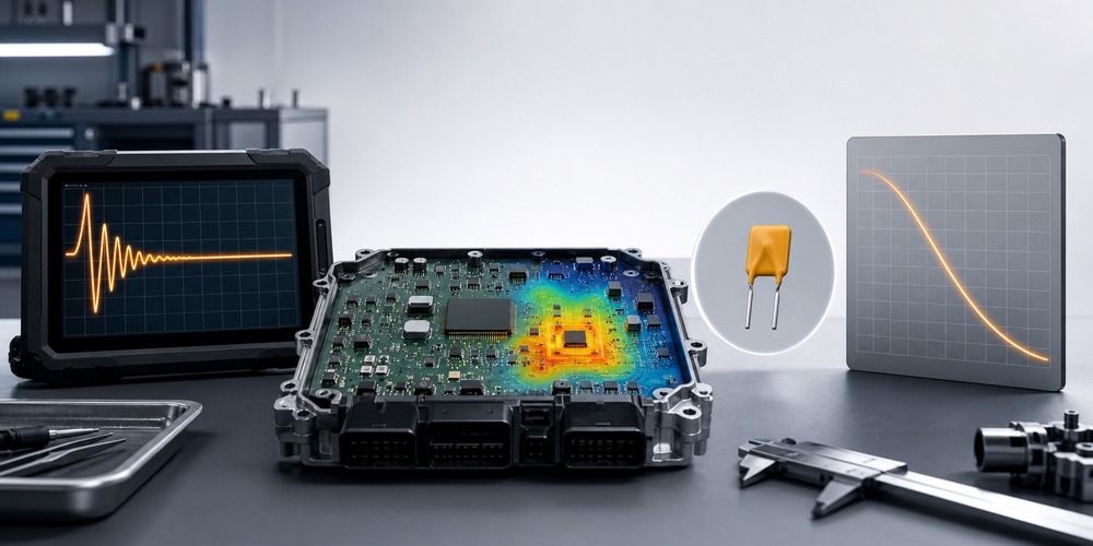
Hold current (Ihold) is the maximum current a PPTC can carry without tripping at a specified temperature. Trip current (Itrip) is the minimum current that drives the device into a high-resistance state at a specified temperature.Fuzetec PPTC technical data notes that in the current region between Ihold and Itrip, the tripping behavior cannot be fully determined. The device may remain in a low-impedance state, or it may shift into a high-impedance state due to initial resistance, ambient temperature, mounting conditions and heat accumulation.
This point is critical for automotive PPTCs. When a design judges only that "normal current is less than Ihold" without re-derating the usable Ihold at high temperature, the actual operating point may be pushed into the uncertain region.
Thermal Derating Is a Selection Condition, Not a Footnote
Thermal derating refers to the adjustment of a device's current-carrying capability as ambient temperature changes. Fuzetec's PPTC selection guide lists thermal derating and environmental conditions among the factors to consider when choosing a PPTC resettable fuse.Stability in room-temperature testing does not imply stability inside a hot enclosure, a sealed module, next to power devices, or under sustained full load. For automotive, EV and industrial control products, what really matters is not the laboratory room temperature, but the actual operating temperature at the location of the PPTC.
Why Are Automotive PPTCs Especially Prone to Derating Problems?
What automotive electronics, the EV supply chain and industrial control equipment have in common is that the product may operate in a far harsher thermal environment than an office or a lab bench. Temperature is not background context; it is a selection condition.Fuzetec company information mentions application directions such as automotive electronics, Industry 4.0, the energy sector and electric vehicles. In practice, these applications usually involve power density, heat dissipation, long operating hours and reliability verification, so protection devices cannot be selected on a single current value alone.
Four Types of Temperature That Must Be Distinguished
"Maximum temperature" is often heard in selection discussions, but the term is not precise enough. It is worth breaking it into at least four types of temperature:| Temperature Condition | Meaning | Effect on the PPTC |
| Datasheet specified temperature | The reference condition at which Ihold/Itrip are stated | The starting point for specification comparison; not equal to actual operating conditions |
| External ambient temperature | Temperature in the cabin, the enclosure or around the equipment | Affects the overall thermal margin |
| Local PCB temperature | Measured temperature at the PPTC pads and surrounding copper | Closer to the real thermal condition of the device |
| Nearby heat source temperature | Heat sources near MOSFETs, power ICs, inductors, connectors or batteries | May raise the temperature around the PPTC above the external ambient |
If the design document only states "ambient 60°C" but there is a MOSFET, inductor or power IC next to the PPTC, the local temperature may differ from the external ambient. This is why the same PPTC placed at different PCB locations can show different tripping behavior.
Startup Inrush Makes the Judgment More Complex
Engineer Ming-Che was responsible for an EV auxiliary control board. The first BOM selected a PPTC based on steady-state current, and room-temperature testing passed. Later, system testing added a startup sequence; the on-board load produced a short peak at power-up, and combined with a high temperature inside the enclosure, the PPTC tripped intermittently. In the end the team did not simply switch to a higher current rating; they re-measured the startup waveform, the maximum board temperature and the fault current, and then went back to the thermal derating curve to check.This example illustrates one key point: startup inrush, short-duration peaks and continuous load current must be considered separately. A PPTC should not necessarily trip on a brief inrush, but avoiding that inrush must not push Itrip so high that the device is no longer sensitive enough during a real fault.
Further reading: if you are building a PPTC selection process, start with Fuzetec's PPTC Resettable Fuse product group, then narrow the range by operating voltage, load current, fault current, ambient temperature and package constraints.
What Two Problems Result from Poorly Calculated Derating?
A PPTC derating error does not only make a design "too sensitive." It can also create the opposite risk: choosing a device too large to avoid nuisance tripping, leaving protection insufficient when a real fault occurs.Problem 1: Early Tripping Under Normal Load
In the first case there is nothing abnormal about the normal load itself, but high temperature reduces the usable Ihold, making the PPTC more likely to approach the trip region.This kind of problem often surfaces late in verification. The reason is that early bring-up is usually done at room temperature, and the load may not be the harshest combination. Only during thermal chamber testing, full load, long operating hours or sealed system testing does the PPTC reveal insufficient thermal margin.
If the problem is misdiagnosed as "unstable parts," the team may spend a lot of time changing suppliers, changing lot codes or changing test conditions. A more effective first step is to put the actual operating point back onto the derating curve and the time-to-trip conditions and check it there.
Problem 2: Choosing Too Large, and Losing Sensitivity During a Fault
The second case is more easily overlooked. To avoid nuisance tripping at high temperature, some designs simply move Ihold up one or several steps. This may make normal operation more stable, but it may also mean that Itrip, fault current and trip time no longer match the original protection objective.For example, if the fault current is limited by the upstream power supply, it may not actually be large enough to drive an oversized PPTC quickly into protection. Downstream wiring, connectors or loads may then carry abnormal current for too long.
PPTC selection is therefore not simply about "not tripping." The correct goal is no nuisance tripping under normal conditions, and current limiting within a design-acceptable time under fault conditions.
High-Temperature PPTC Selection Flow: Put Temperature and Current in the Same Table
Fuzetec's PPTC selection guide lists factors including operating voltage, hold current, trip current, maximum voltage, maximum current, time-to-trip, thermal derating, environmental conditions and certification requirements. For high-temperature automotive and industrial control applications, it is better to organize this data into a single table rather than scattering it across different test records.Step 1: Confirm the Maximum Continuous Load Current
First distinguish between average current, maximum continuous current, full-load current and short-duration peaks. The Ihold of a PPTC should correspond to the current that must be carried for a long time under normal conditions, not just one typical value.Step 2: Confirm Startup Inrush and Short-Duration Peaks
Motors, capacitive inputs, power conversion, communication modules or sensor arrays can all produce instantaneous current at power-up or during mode changes. These waveforms need to be confirmed with an oscilloscope or system test records; they cannot be estimated from steady-state current alone.Step 3: Confirm the Maximum Ambient Temperature and the Measured Temperature Around the PPTC
Do not record only the thermal chamber setting. Measure local temperatures on the PCB near the PPTC, at nearby power devices, inside the enclosure and with the system at full load.If the product has multiple mounting orientations or different cooling conditions, the worst case should also be included in verification.
Step 4: Check the Datasheet Thermal Derating Curve
Take the actual maximum temperature back to the thermal derating curve in the datasheet and confirm whether the usable hold current at that temperature is still higher than the maximum normal continuous current.If the operating point sits close to the boundary, you need to look further into Itrip, time-to-trip, resistance, PCB heat dissipation and long-term heat accumulation.
Step 5: Go Back and Check Itrip, Vmax, Imax, Time-to-Trip and Resistance
Avoid solving nuisance tripping at the expense of fault protection. During selection, confirm the following at the same time:- Whether the operating voltage is below the device's permitted condition.
- Whether the possible fault current is within the device's withstand range.
- Whether the fault current is sufficient to drive the PPTC into protection.
- Whether time-to-trip matches the withstand conditions of downstream components, wiring and connectors.
- Whether the normal-state resistance causes unnecessary voltage drop, power loss or temperature rise.
Step 6: Run Thermal Chamber, Full-Load, Startup, Short-Circuit and Repeated Fault Tests
The datasheet is the starting point of selection, not the end of verification. For automotive, EV and industrial control products, it is advisable to use an actual board to confirm high-temperature full load, power-up inrush, short circuit or overload, recovery after the fault is removed, and thermal stability over long operation.High-Temperature PPTC Selection Checklist
Purchasing staff can use this table too. When a supplier receives only "we need a 1A PPTC," it is hard to judge the real requirement. If voltage, load, fault conditions, temperature and package are provided at the same time, the selection discussion moves much closer to the real problem.| Check Item | Why It Matters | Information to Provide |
| Operating voltage | Avoid exceeding the device rating | Maximum operating voltage, possible abnormal voltage |
| Maximum continuous current | Judge whether the usable Ihold after derating is sufficient | Normal, full-load and peak current |
| Startup inrush | Avoid mistaking a short peak for a steady-state condition | Peak amplitude, duration, frequency of occurrence |
| Fault current | Judge whether the device can enter protection | Overload, short circuit, upstream current limiting |
| Maximum temperature | Apply thermal derating | Ta, measured PCB points, thermal chamber conditions |
| Package and heat dissipation | Affects actual temperature rise and operating time | SMD, radial, copper area, space, height |
| Verification conditions | Confirm risk before mass production | Thermal chamber, full load, startup and short-circuit tests |
How Do High-Temperature Applications Map to Fuzetec Product Categories?
Only after the design conditions are understood is it appropriate to move on to product category comparison. Fuzetec's PPTC Resettable Fuse product group includes Radial Leaded PPTC, SMD PPTC, High Voltage Series, High Temperature Series, Battery Strap, and Chip & Disc PPTC.If the application focus is high temperature and thermal derating, start with the High Temperature Series high-temperature PPTC. That page lists the FHT Series and FSMDH Series and indicates operating temperature range information for the relevant series. Such data can be used for initial screening, but it cannot replace the datasheet and actual circuit verification.
If board space is limited, you can compare SMD PPTC. If the application involves battery pack structures, connecting straps or welded forms, you can further evaluate whether the Battery Strap type is relevant based on mechanical and electrical conditions.
Industrial control engineer Chih-Hao once encountered a purchasing substitution problem. The original design was stable at room temperature, but during a shortage a similar-looking part number was used instead. The new part fit the PCB in package size, but after full load at high temperature the system restarted intermittently. Only when the team went back through the documents did they find that the two parts were not equivalent in high-temperature derating, resistance and operating time. Such substitutions should not be compared on hold current alone; Itrip, resistance, package heat dissipation and test conditions must be compared as well.
Need to narrow down part numbers? Prepare the operating voltage, normal load current, fault current, maximum ambient temperature, measured temperature around the PPTC and package constraints, then discuss suitable PPTC product directions through the Fuzetec contact page.
FAQ: Common Questions About Automotive PPTC Derating
Does a PPTC tripping early at high temperature mean the device has failed?
Not necessarily. Early tripping at high temperature is often caused by actual operating conditions exceeding the margin estimated at room temperature. PPTC behavior is affected by ambient temperature, initial resistance, mounting conditions and heat accumulation. Start by rechecking the datasheet, the thermal derating curve, measured PCB temperature and the actual current waveform.Is it enough for Ihold to be greater than the normal operating current?
No. Ihold is the hold current at a specified temperature. High-temperature applications need to confirm the usable hold current after derating at that temperature, and check Itrip, time-to-trip, resistance and fault current at the same time.Must automotive electronics always use a high-temperature series PPTC?
Not necessarily. The high-temperature series is an important screening direction, but suitability still depends on operating voltage, load current, fault current, the temperature curve, package constraints and actual testing. Do not skip the full selection process just because the application is automotive.Why does the same PPTC behave differently on different PCBs?
A PPTC is a thermally sensitive device. Mounting conditions, copper area, nearby heat sources, airflow, the enclosure and component placement all affect the actual temperature rise. The same part number on a different PCB, or at a different location, can show different trip times and holding capability.To avoid nuisance tripping, is it acceptable to choose one step higher on Ihold?
It can be evaluated as one direction, but Ihold alone is not enough. If, after increasing Ihold, the fault current is not sufficient to drive the PPTC into protection within an acceptable time, overcurrent protection may actually be weakened. Confirm Itrip, fault current, time-to-trip and the withstand capability of downstream components at the same time.Conclusion: High-Temperature PPTC Selection Must Avoid Both Nuisance Tripping and Insufficient Protection
Early tripping of an automotive PPTC usually cannot be explained by "bad parts" or "the current rating was too low." A more common cause is that room-temperature Ihold, actual high temperature, local PCB temperature rise, startup inrush and fault current were never judged within the same selection framework.The correct approach is to define operating voltage, maximum continuous current, startup peak, possible fault current and maximum measured temperature first, then check the operating point against the datasheet thermal derating curve. After that, go back and confirm Itrip, time-to-trip, resistance, package heat dissipation and prototype test results.
If your design has already reached thermal chamber, reliability or pre-production verification, it is better not to treat early PPTC tripping as a case of "just go one size up." Organize the conditions completely, then confirm against the PPTC selection guide and actual testing. That is much closer to the selection approach that high-reliability applications require.
Next step: provide your operating voltage, normal load current, possible fault current, maximum ambient temperature, measured PCB temperature rise and package constraints, and ask Fuzetec to help confirm PPTC selection.
Sources
- Fuzetec PPTC technical inquiry: https://www.fuzetec.com/en/applications/technical-inquiry-pptc
- Fuzetec PPTC fundamentals: https://www.fuzetec.com/en/news-detail/pptc-resettable-fuse-fundamentals
- Fuzetec PPTC selection guide: https://www.fuzetec.com/en/news-detail/pptc-resettable-fuse-selection-guide
- Fuzetec PPTC Resettable Fuse product group: https://www.fuzetec.com/en/product-group/pptc-resettable-fuse
- Fuzetec High Temperature Series: https://www.fuzetec.com/en/product-lists/high-temperature-series
- Google SEO Starter Guide: https://developers.google.com/search/docs/fundamentals/seo-starter-guide
- Schema.org FAQPage: https://schema.org/FAQPage
Tag