Table of Contents
- Why ODM Protection Component Design-In Cannot Rely on the Datasheet Alone
- Pre-Production Check 1: Actual Operating Voltage and Maximum Possible Voltage
- Pre-Production Check 2: Normal Load Current, Inrush Current, and Current Waveform
- Pre-Production Check 3: Fault Current, Short-Circuit Current, and Fault Removability
- Pre-Production Check 4: Ihold, Itrip, and the Uncertain Region
- Pre-Production Check 5: Whether Time-to-Trip Protects the Downstream Circuit
- Pre-Production Check 6: Thermal Derating, Ambient Temperature, and Mechanical Heat Flow
- Pre-Production Check 7: Package, PCB Layout, and Manufacturing Constraints
- ODM/OEM Design-In Checklist
- How Fuzetec Supports Protection Component Design-In Discussions
- FAQ
ODM protection component design-in should never stop at a single headline rating in the datasheet. Before production, engineering teams need to validate the real operating voltage, normal and fault current, Ihold and Itrip behavior, thermal derating, time-to-trip, package and PCB layout constraints, environmental conditions, compliance requirements, and prototype test data. A datasheet is the starting point for part selection; production reliability has to be proven against the product's actual electrical, thermal, and fault conditions.
A familiar scenario: an ODM hardware engineer selects a PPTC resettable fuse for an external IoT device during EVT. Room-temperature startup and short-circuit tests look fine. Later, during DVT, the unit occasionally drops power under sustained full-load operation inside a closed enclosure at elevated temperature. The issue is not that the selected part has an unattractive rating. The issue is that thermal derating, nearby heat sources, copper area, enclosure temperature, and the real load profile were not evaluated together during design-in.
This article translates protection component selection into a practical production-readiness checklist for ODM/OEM teams, brand customers, hardware engineering, quality, and sourcing. It focuses on how to turn PPTC datasheet parameters and circuit protection requirements into conditions that can be reviewed, tested, and approved before mass production.
Key Takeaways
Protection component selection is therefore not a table-comparison exercise. It is a cross-functional engineering process: hardware defines circuit conditions, mechanical engineering defines thermal and space limits, quality confirms test and compliance requirements, sourcing checks supply and second-source risk, and the brand customer confirms the operating profile.
PPTC resettable fuses are primarily used for resettable overcurrent protection. If an external port is also exposed to ESD or transient voltage, do not assume a PPTC can replace MOV varistors, TVS diodes, or Hybrid Protection (PPTC+MOV) design approaches.
IEC 61000-4-2:2008 relates to electrostatic-discharge immunity testing, while IEC 61000-4-4:2012 relates to electrical fast transient/burst immunity testing. These test contexts are a useful reminder that field risk is not always a long-duration overcurrent event.
That means an ODM team should not only ask whether Ihold is high enough. Ask what temperature the component sees inside the enclosure, whether it sits near a MOSFET, charger IC, power inductor, or battery, whether the copper area provides enough heat spreading, and whether soldering, coating, potting, or mechanical coverage will change the thermal path in production.
If a brand customer requests a second source before PVT, a sourcing team may find a part with similar appearance and ratings. If hardware only compares package, voltage rating, and hold current, the team may miss differences in initial resistance, trip curves, thermal derating, certifications, and test data. Use Fuzetec's Cross Reference as a starting point, but always revalidate electrical, thermal, package, and test conditions for any alternate part.
ODM/OEM teams should define normal operating voltage, maximum possible input voltage, startup and shutdown transients, user plug/unplug behavior, reverse connection, hot-plug events, adapter variation, and brand-customer test conditions. If the component sits on an external port, include cable length, grounding, long-line coupling, and external interference.
For PPTC selection, working voltage is a baseline requirement. Fuzetec's PPTC selection guide lists operating voltage as one of the factors for selecting a PPTC resettable fuse. If the design risk is surge, ESD, or transient voltage, return to the Overvoltage Protection product group and evaluate whether MOV varistors, TVS diodes, or hybrid protection should be part of the architecture.
Many products have modest steady-state current but very different current waveforms during startup, motor spin-up, capacitor charging, wireless transmission, backlight turn-on, or battery charge/discharge transitions. If the ODM team compares only average current against datasheet Ihold, it may underestimate nuisance-trip risk.
Ihold is the maximum current a PPTC device can carry without tripping under specified conditions. Itrip is the current required to trigger the device into its high-resistance state. Both parameters need to be evaluated with ambient temperature, thermal derating, and the actual waveform.
For example, a handheld device may show a stable charging waveform on the lab bench. In the field, a user may charge it in a hot environment while wireless transmission and backlight are active. Steady-state current, periodic peaks, and enclosure temperature rise at the same time. The available PPTC margin is no longer the same as a room-temperature bench test.
Common ODM product faults include external-port short circuits, wiring errors, downstream module failures, overloads, harness wear, or user-created transient faults. If the product needs to recover after the fault is removed, the resettable behavior of a PPTC may be valuable.
However, if the fault is non-recoverable, requires forced isolation, or is tied to a specific safety strategy, do not select a device simply because resettable protection seems convenient. Go back to the product safety requirements, system architecture, regulatory constraints, and customer test plan.
Fault current is not a single number. Confirm maximum short-circuit current, fault duration, upstream power-source limits, battery or adapter capability, and how long downstream circuits can tolerate the fault condition.
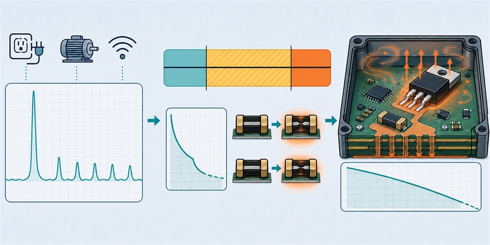
According to Fuzetec's PPTC fundamentals, Ihold is the maximum current the device can carry without tripping at a rated temperature, while Itrip is the minimum current required to trip the device at a rated temperature. The current region between Ihold and Itrip is not fully deterministic and is affected by initial resistance, ambient temperature, and mounting conditions.
For design-in review, replace the shortcut "Ihold is greater than load current" with better engineering questions:
If the downstream load includes connectors, harnesses, battery terminals, power ICs, MOSFETs, sensors, or communication modules, confirm whether the fault current before protection action creates unacceptable thermal, electrical, or functional risk. Time-to-trip changes with fault current, so review the curve rather than a single table entry.
In one common ODM development pattern, the first power-board build verifies steady-state current and confirms that the design enters protection after a short. During DVT, the brand customer adds a miswiring test and the downstream connector shows more temperature rise than expected. The lesson is not that PPTC protection is ineffective; it is that time-to-trip was not tied to downstream withstand time in the validation plan.
ODM teams should provide concrete conditions: maximum internal enclosure temperature, nearby heat sources, PCB layer count and copper area, airflow or sealed-space assumptions, potting or conformal coating, product duty cycle, and brand-customer high-temperature test requirements.
If the product operates at elevated ambient temperature, the discussion may extend to Fuzetec's High Temperature Series. Suitability still depends on the specific datasheet, derating curve, layout, and application test results.
Fuzetec's PPTC Resettable Fuse product group includes Radial Leaded PPTC, SMD PPTC, High Voltage Series, High Temperature Series, Battery Strap, and Chip & Disc PPTC options. These categories are useful starting points for design-in discussions, but they do not replace part-level specification review.
For high-density PCBs, evaluate whether an SMD PPTC meets space and manufacturing needs. For battery-pack or welded-tab applications, Battery Strap types may be more relevant. For through-hole or plug-in designs, Radial Leaded PPTC options may be the starting point.
Layout needs equal attention. Proximity to heat sources, insufficient copper area, narrow traces, unsuitable pad design, or production-process changes that alter heat flow can change the real protection behavior.
Fuzetec company information references UL, C-UL(CSA), TUV certifications and an ISO 9001-2000 quality management system. Treat these as company-level or product-family context; part-number approval still needs the product page, datasheet, catalog, or supplier documentation.
Before production, ODM/OEM teams should align on:
Recommended design-in flow: define the fault type first; confirm voltage, current, thermal, and package conditions; select the protection component category; compare the datasheet and characteristic curves; then validate the result with prototype testing.
After the checklist is complete, use Fuzetec's Product Search to start narrowing product categories. If the conditions are still uncertain, contact Fuzetec with the application conditions and discuss the right selection path.
Based on Fuzetec's product categories, the company provides PPTC Resettable Fuse, Overvoltage Protection, and Power MOSFET product groups. For this topic, PPTC Resettable Fuse products map to resettable overcurrent protection. Overvoltage Protection should be part of the discussion when the design also involves MOV varistors, TVS diodes, Hybrid Protection (PPTC+MOV), surge, or ESD protection.
If your design is primarily an overcurrent risk, the discussion should focus on operating voltage, Ihold, Itrip, fault current, time-to-trip, thermal derating, and package. If an external port or power input is also exposed to transient voltage, define the overvoltage protection requirement separately so the PPTC is not asked to solve a protection problem outside its role.
For an efficient design-in review, prepare the operating voltage range, normal current waveform, possible fault current, ambient temperature, PCB layout constraints, package requirements, customer test conditions, compliance-document needs, and any candidate part numbers or BOM lines.
PPTC resettable fuses are useful for resettable overcurrent protection where the fault can be removed, but they are not a universal answer to every protection problem. If the design involves surge, ESD, or transient voltage, overvoltage protection components should be evaluated separately.
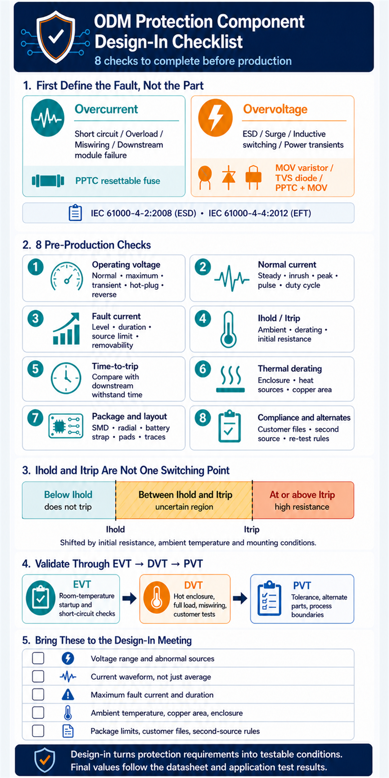
A familiar scenario: an ODM hardware engineer selects a PPTC resettable fuse for an external IoT device during EVT. Room-temperature startup and short-circuit tests look fine. Later, during DVT, the unit occasionally drops power under sustained full-load operation inside a closed enclosure at elevated temperature. The issue is not that the selected part has an unattractive rating. The issue is that thermal derating, nearby heat sources, copper area, enclosure temperature, and the real load profile were not evaluated together during design-in.
This article translates protection component selection into a practical production-readiness checklist for ODM/OEM teams, brand customers, hardware engineering, quality, and sourcing. It focuses on how to turn PPTC datasheet parameters and circuit protection requirements into conditions that can be reviewed, tested, and approved before mass production.
Key Takeaways
- The point of ODM protection component design-in is not to find a part that only matches a nominal rating. It is to define voltage, current, fault, thermal, package, layout, and validation conditions clearly enough for production.
- In a normal state, a PPTC resettable fuse provides a low-resistance conductive path. Under abnormal current, self-heating increases resistance and limits current.
- Ihold and Itrip must be evaluated with ambient temperature, installation conditions, initial resistance, thermal derating, and the actual current waveform.
- Before production, datasheet-based selection should be converted into EVT, DVT, and PVT test conditions to avoid late-stage surprises during customer qualification, second-source review, or production ramp.
- Fuzetec's PPTC Resettable Fuse product group can support overcurrent protection discussions. If the design also faces surge, ESD, or transient-voltage exposure, overvoltage protection components should be evaluated separately.
Why ODM Protection Component Design-In Cannot Rely on the Datasheet Alone
A datasheet defines the component's rating range, test conditions, and characteristic curves. It does not define your product's fault model. A real ODM product includes a power architecture, load waveform, mechanical thermal path, PCB layout, brand-customer test requirements, production process, and field-use environment.Protection component selection is therefore not a table-comparison exercise. It is a cross-functional engineering process: hardware defines circuit conditions, mechanical engineering defines thermal and space limits, quality confirms test and compliance requirements, sourcing checks supply and second-source risk, and the brand customer confirms the operating profile.
The datasheet does not define the fault mode for you
The phrase "protection component" can refer to very different risks. Overcurrent protection addresses abnormal current events such as short circuits, overloads, wiring errors, or downstream load failures. Overvoltage protection addresses abnormal voltage events such as ESD, surge, inductive load switching, or power transients.PPTC resettable fuses are primarily used for resettable overcurrent protection. If an external port is also exposed to ESD or transient voltage, do not assume a PPTC can replace MOV varistors, TVS diodes, or Hybrid Protection (PPTC+MOV) design approaches.
IEC 61000-4-2:2008 relates to electrostatic-discharge immunity testing, while IEC 61000-4-4:2012 relates to electrical fast transient/burst immunity testing. These test contexts are a useful reminder that field risk is not always a long-duration overcurrent event.
The same component can behave differently under different thermal conditions
Fuzetec's PPTC fundamentals explain that conductive particles in the polymer structure create a conductive path during normal operation. When fault current heats the material, resistance rises sharply and limits current. The region between Ihold and Itrip is affected by initial resistance, ambient temperature, and installation conditions.That means an ODM team should not only ask whether Ihold is high enough. Ask what temperature the component sees inside the enclosure, whether it sits near a MOSFET, charger IC, power inductor, or battery, whether the copper area provides enough heat spreading, and whether soldering, coating, potting, or mechanical coverage will change the thermal path in production.
Production risk often appears at boundary conditions
EVT builds are small and usually tested under a limited set of conditions. Once production begins, component tolerance, ambient temperature, load variation, user behavior, and alternate sourcing can push the design closer to its real limits.If a brand customer requests a second source before PVT, a sourcing team may find a part with similar appearance and ratings. If hardware only compares package, voltage rating, and hold current, the team may miss differences in initial resistance, trip curves, thermal derating, certifications, and test data. Use Fuzetec's Cross Reference as a starting point, but always revalidate electrical, thermal, package, and test conditions for any alternate part.
Pre-Production Check 1: Actual Operating Voltage and Maximum Possible Voltage
The first question is not "What is the maximum rating of this protection component?" The better question is "What voltage will this node see under normal and abnormal conditions?"ODM/OEM teams should define normal operating voltage, maximum possible input voltage, startup and shutdown transients, user plug/unplug behavior, reverse connection, hot-plug events, adapter variation, and brand-customer test conditions. If the component sits on an external port, include cable length, grounding, long-line coupling, and external interference.
For PPTC selection, working voltage is a baseline requirement. Fuzetec's PPTC selection guide lists operating voltage as one of the factors for selecting a PPTC resettable fuse. If the design risk is surge, ESD, or transient voltage, return to the Overvoltage Protection product group and evaluate whether MOV varistors, TVS diodes, or hybrid protection should be part of the architecture.
Pre-Production Check 2: Normal Load Current, Inrush Current, and Current Waveform
The second question is normal current, but "normal" cannot mean only average current.Many products have modest steady-state current but very different current waveforms during startup, motor spin-up, capacitor charging, wireless transmission, backlight turn-on, or battery charge/discharge transitions. If the ODM team compares only average current against datasheet Ihold, it may underestimate nuisance-trip risk.
Ihold is the maximum current a PPTC device can carry without tripping under specified conditions. Itrip is the current required to trigger the device into its high-resistance state. Both parameters need to be evaluated with ambient temperature, thermal derating, and the actual waveform.
For example, a handheld device may show a stable charging waveform on the lab bench. In the field, a user may charge it in a hot environment while wireless transmission and backlight are active. Steady-state current, periodic peaks, and enclosure temperature rise at the same time. The available PPTC margin is no longer the same as a room-temperature bench test.
Pre-Production Check 3: Fault Current, Short-Circuit Current, and Fault Removability
PPTC resettable fuses are well suited for overcurrent scenarios where repeat protection is useful and the fault can be removed. That assumption matters.Common ODM product faults include external-port short circuits, wiring errors, downstream module failures, overloads, harness wear, or user-created transient faults. If the product needs to recover after the fault is removed, the resettable behavior of a PPTC may be valuable.
However, if the fault is non-recoverable, requires forced isolation, or is tied to a specific safety strategy, do not select a device simply because resettable protection seems convenient. Go back to the product safety requirements, system architecture, regulatory constraints, and customer test plan.
Fault current is not a single number. Confirm maximum short-circuit current, fault duration, upstream power-source limits, battery or adapter capability, and how long downstream circuits can tolerate the fault condition.
Pre-Production Check 4: Ihold, Itrip, and the Uncertain Region
Ihold and Itrip are the PPTC datasheet parameters most often used for quick comparison. They are also the parameters most often oversimplified.According to Fuzetec's PPTC fundamentals, Ihold is the maximum current the device can carry without tripping at a rated temperature, while Itrip is the minimum current required to trip the device at a rated temperature. The current region between Ihold and Itrip is not fully deterministic and is affected by initial resistance, ambient temperature, and mounting conditions.
For design-in review, replace the shortcut "Ihold is greater than load current" with better engineering questions:
- Is the product's highest normal operating current below the effective hold capability after derating?
- Can startup or pulse current fall into the uncertain region between Ihold and Itrip?
- Is the fault current high enough to move the device into protection within an acceptable time?
- Do the real PCB, enclosure, and ambient-temperature conditions shift these boundaries?
Pre-Production Check 5: Whether Time-to-Trip Protects the Downstream Circuit
Time-to-trip is the time required for a PPTC device to transition from a low-resistance state to a high-resistance current-limiting state under overcurrent conditions. It must be evaluated against the tolerance of the circuit being protected.If the downstream load includes connectors, harnesses, battery terminals, power ICs, MOSFETs, sensors, or communication modules, confirm whether the fault current before protection action creates unacceptable thermal, electrical, or functional risk. Time-to-trip changes with fault current, so review the curve rather than a single table entry.
In one common ODM development pattern, the first power-board build verifies steady-state current and confirms that the design enters protection after a short. During DVT, the brand customer adds a miswiring test and the downstream connector shows more temperature rise than expected. The lesson is not that PPTC protection is ineffective; it is that time-to-trip was not tied to downstream withstand time in the validation plan.
Pre-Production Check 6: Thermal Derating, Ambient Temperature, and Mechanical Heat Flow
Thermal derating is not optional in PPTC selection. Ambient temperature changes the hold-current capability of the device, and the closer the design is to the thermal boundary, the less useful a room-temperature rating becomes.ODM teams should provide concrete conditions: maximum internal enclosure temperature, nearby heat sources, PCB layer count and copper area, airflow or sealed-space assumptions, potting or conformal coating, product duty cycle, and brand-customer high-temperature test requirements.
If the product operates at elevated ambient temperature, the discussion may extend to Fuzetec's High Temperature Series. Suitability still depends on the specific datasheet, derating curve, layout, and application test results.
Pre-Production Check 7: Package, PCB Layout, and Manufacturing Constraints
Package is not a sourcing detail to confirm at the end. It is part of the protection behavior. SMD, radial leaded, battery strap, chip, and disc packages each imply different PCB space, process flow, thermal behavior, mounting method, and application fit.Fuzetec's PPTC Resettable Fuse product group includes Radial Leaded PPTC, SMD PPTC, High Voltage Series, High Temperature Series, Battery Strap, and Chip & Disc PPTC options. These categories are useful starting points for design-in discussions, but they do not replace part-level specification review.
For high-density PCBs, evaluate whether an SMD PPTC meets space and manufacturing needs. For battery-pack or welded-tab applications, Battery Strap types may be more relevant. For through-hole or plug-in designs, Radial Leaded PPTC options may be the starting point.
Layout needs equal attention. Proximity to heat sources, insufficient copper area, narrow traces, unsuitable pad design, or production-process changes that alter heat flow can change the real protection behavior.
Pre-Production Check 8: Compliance, Alternate Parts, and Supplier Collaboration
The last item is often underestimated: documentation and cross-team alignment. Protection component selection supports not only hardware function, but also certification files, customer approval documents, environmental documentation, alternate-part management, and production supply.Fuzetec company information references UL, C-UL(CSA), TUV certifications and an ISO 9001-2000 quality management system. Treat these as company-level or product-family context; part-number approval still needs the product page, datasheet, catalog, or supplier documentation.
Before production, ODM/OEM teams should align on:
- Which safety, environmental, and reliability documents the brand customer requires.
- Whether second-source or alternate parts are permitted.
- Which electrical, thermal, mechanical, or certification tests must be repeated for an alternate part.
- Whether sourcing and engineering are using the same specification checklist.
- Whether a production change requires renewed customer approval.
ODM/OEM Design-In Checklist
Use the following checklist as the baseline input list for an ODM protection component design-in meeting. It is not a substitute for datasheet selection. It helps hardware, quality, sourcing, and the supplier speak the same engineering language before a part moves toward production.| Checklist Item | Information to Provide | Why It Matters |
| Operating voltage | Normal, maximum, abnormal, and transient voltage sources | Avoid selecting only against nominal voltage |
| Normal current | Steady-state, inrush, peak, pulse, and duty-cycle current | Evaluate Ihold and nuisance-trip risk |
| Fault current | Short circuit, overload, miswiring, and downstream failure current | Define protection strategy and maximum fault conditions |
| Ihold / Itrip | Hold current, trip current, and uncertain operating region | Avoid treating parameters as absolute switching thresholds |
| Time-to-trip | Trip timing under fault current and downstream withstand limits | Confirm protection timing fits the circuit need |
| Thermal conditions | Ambient temperature, enclosure, copper area, nearby heat sources | Evaluate derating and production boundary conditions |
| Package and layout | PCB space, height, pads, process, and heat spreading | Avoid PVT or production-stage implementation issues |
| Compliance and alternates | Safety, environmental, customer files, and second-source rules | Avoid late certification or supply-chain gaps |
| Test plan | EVT, DVT, and PVT conditions with acceptance criteria | Convert datasheet selection into verifiable results |
After the checklist is complete, use Fuzetec's Product Search to start narrowing product categories. If the conditions are still uncertain, contact Fuzetec with the application conditions and discuss the right selection path.
How Fuzetec Supports Protection Component Design-In Discussions
Fuzetec should not be understood as guaranteeing that one component will pass every product-level test in every customer design. The practical value is helping engineering teams ask the right selection questions with circuit protection and materials experience.Based on Fuzetec's product categories, the company provides PPTC Resettable Fuse, Overvoltage Protection, and Power MOSFET product groups. For this topic, PPTC Resettable Fuse products map to resettable overcurrent protection. Overvoltage Protection should be part of the discussion when the design also involves MOV varistors, TVS diodes, Hybrid Protection (PPTC+MOV), surge, or ESD protection.
If your design is primarily an overcurrent risk, the discussion should focus on operating voltage, Ihold, Itrip, fault current, time-to-trip, thermal derating, and package. If an external port or power input is also exposed to transient voltage, define the overvoltage protection requirement separately so the PPTC is not asked to solve a protection problem outside its role.
For an efficient design-in review, prepare the operating voltage range, normal current waveform, possible fault current, ambient temperature, PCB layout constraints, package requirements, customer test conditions, compliance-document needs, and any candidate part numbers or BOM lines.
FAQ
Can Ihold in a PPTC datasheet be treated as the product's maximum operating current?
No. Ihold should be evaluated with ambient temperature, thermal derating, mounting conditions, initial resistance, startup current, and the real duty cycle. The region between Ihold and Itrip is affected by temperature and installation conditions, so a direct one-number comparison is not enough for production design-in.Why can the same PPTC pass in the lab but nuisance-trip after production?
Common causes include higher internal enclosure temperature, added nearby heat sources, different PCB heat spreading, changed load waveform, process or material variation, and test plans that did not cover production boundary conditions. This is why ODM protection component design-in should be validated progressively through EVT, DVT, and PVT.When should an ODM involve the supplier in protection component design-in?
As early as possible, ideally when the power architecture, external ports, battery path, or high-risk loads are being defined. Waiting until PVT or customer approval can make package, layout, thermal, or documentation changes much harder.Can a PPTC solve both overcurrent and overvoltage problems?
A PPTC resettable fuse is primarily used for resettable overcurrent protection. If the product faces ESD, surge, or transient voltage, evaluate overvoltage protection components such as MOV varistors, TVS diodes, or Hybrid Protection (PPTC+MOV). The final protection approach still depends on the datasheet, test standard, layout, and application conditions.What must be rechecked when a brand customer requests an alternate part?
At minimum, recheck operating voltage, Ihold, Itrip, maximum fault conditions, time-to-trip, initial resistance, thermal derating, package dimensions, soldering conditions, safety and environmental documents, and prototype test results. Matching package and rated current is usually not enough for a production alternate.What do ODM teams most often miss in protection component design-in?
They most often miss the real application conditions. A team may read the datasheet but fail to bring startup current, fault current, ambient temperature, mechanical heat flow, PCB layout, customer testing, alternate-part documentation, and production process into one checklist.Conclusion: Design-In Turns Protection Requirements Into Testable Conditions
The core of ODM protection component design-in is not reading a datasheet faster. It is validating datasheet parameters against the real product environment. Operating voltage, normal current, fault current, Ihold and Itrip, time-to-trip, thermal derating, package, layout, compliance documents, and the test plan all influence production reliability.PPTC resettable fuses are useful for resettable overcurrent protection where the fault can be removed, but they are not a universal answer to every protection problem. If the design involves surge, ESD, or transient voltage, overvoltage protection components should be evaluated separately.
Next Steps
The next step is practical: complete the eight-item checklist, organize voltage, current, fault, thermal, package, and test requirements, then use Fuzetec's Product Search or Contact Us to discuss the selection path. The earlier protection requirements become testable conditions, the lower the risk of late-stage redesign and production communication cost.
Sources
- Fuzetec PPTC selection guide
- Fuzetec PPTC fundamentals
- Fuzetec PPTC fuse explained
- IEC 61000-4-2:2008
- IEC 61000-4-4:2012
Tag