Why Equipment Stops at Night: Industrial Equipment Downtime Causes and Protection Fixes

Table of Contents
Identify industrial equipment downtime causes by synchronizing event records, then match protection to the measured electrical fault.
Fuzetec Industrial Automation & IoT Application Engineering Team | Industrial Automation & IoT Application Engineer | English (US) | Published 2026-09-21
Check what differs overnight. HVAC setback can reduce cabinet cooling; an unattended recipe can sustain a higher thermal load; scheduled motors can change supply loading. Also compare PLC schedules, network maintenance, interlocks and shift procedures. Night-time timing is a clue, not proof of an electrical fault.
Recovery can obscure the sequence without erasing every record. A power supply may retry after an overload, and a controller may restart after a watchdog timeout. A PPTC can remain hot and resistive while energized; removing or reducing power and allowing cooling may be needed for recovery. Preserve logs before resetting equipment.
For illustration only, a 1.0 A rated hold current multiplied by a hypothetical 0.60 temperature factor becomes 0.60 A. A 0.65 A continuous load then exceeds the guaranteed hold capability; the exact trip time still requires the relevant curve and testing. These numbers are not a Fuzetec product specification.
Distinguish surge from electrical fast transients, voltage dips and noise. A fuse or PPTC does not clamp a voltage spike. Clamping, suppression at the source, cable routing and grounding may all matter, depending on the measured disturbance.
Rittal describes enclosure heating and moisture management as ways to address this mechanism [2]. Select sealing, heaters or dehumidification for the actual environment; arbitrary ventilation can introduce humid or contaminated air.
A motor controller that trips at startup presents a related diagnostic clue: acceptable steady current does not prove startup margin. Also inspect terminals and connectors under the appropriate isolation procedure. A high-resistance connection can create intermittent drops without exceeding a fuse rating.
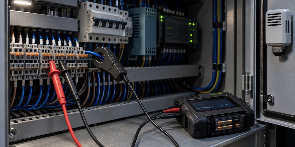
Continue recording across the relevant night cycles. If the PLC loses power too, use an independently powered recorder or retained event storage; an input that disappears with the controller cannot reliably preserve the fault.
For faster and more precise current control, an electronic fuse or electronic circuit protector may suit the branch; TI’s PLC reference design illustrates this approach [3]. A conventional fuse requires suitable breaking capacity and coordination. TVS diodes can clamp transients, but selection must consider operating voltage, clamping voltage, pulse energy and layout, not just nominal rail voltage.
Protection cannot correct a PLC logic error, worn bearing, misaligned sensor or communication timeout. Electrical measurements should establish the need before components are changed.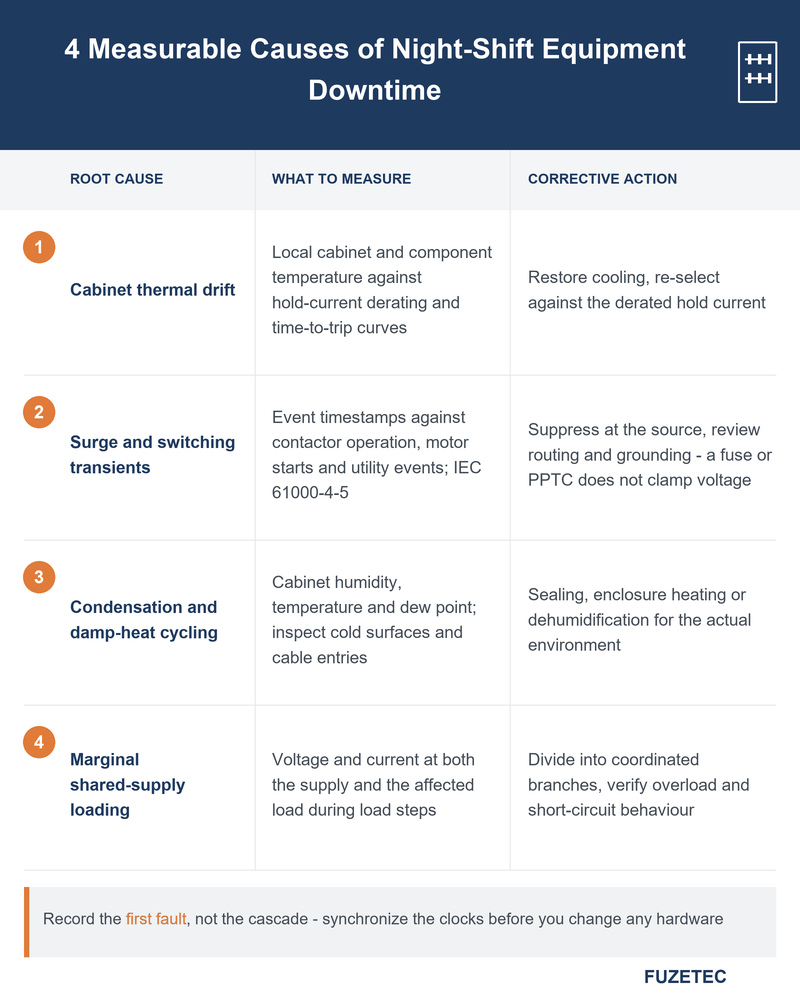
Compare this with engineering, components, installation and validation costs. Separate time lost to the fault from time waiting for someone to respond; logging and remote notification may reduce the latter even before the hardware fix is complete. Track these measures before and after the change to assess reliability gains.
[2] Rittal — Preventing condensation in enclosures
[3] Texas Instruments — TIDA-00233 PLC protection reference design
Fuzetec Industrial Automation & IoT Application Engineering Team | Industrial Automation & IoT Application Engineer | English (US) | Published 2026-09-21
Why the Fault Waits for the Night Shift
Imagine a line that runs through two shifts, stops at 02:40, and restarts after an operator cycles power. By morning the indicators are green. This illustrative scenario shows why industrial equipment downtime causes are difficult to confirm: the conditions and the evidence may both have changed before maintenance arrives.Check what differs overnight. HVAC setback can reduce cabinet cooling; an unattended recipe can sustain a higher thermal load; scheduled motors can change supply loading. Also compare PLC schedules, network maintenance, interlocks and shift procedures. Night-time timing is a clue, not proof of an electrical fault.
Recovery can obscure the sequence without erasing every record. A power supply may retry after an overload, and a controller may restart after a watchdog timeout. A PPTC can remain hot and resistive while energized; removing or reducing power and allowing cooling may be needed for recovery. Preserve logs before resetting equipment.
Industrial Equipment Downtime Causes You Can Actually Measure
Strip away the guesswork and the electrical root causes behind unexplained night stoppages fall into four measurable groups, each with its own fingerprint and its own fix.Thermal drift inside the control cabinet
A PPTC responds to heating, so its current capability depends on local temperature. A device that holds the normal load on a cool bench may not hold it in a hot cabinet. Check the actual part’s temperature derating and time-to-trip curves, including startup pulses and component heating nearby. The Fuzetec PPTC resettable fuse selection guide explains the selection inputs.For illustration only, a 1.0 A rated hold current multiplied by a hypothetical 0.60 temperature factor becomes 0.60 A. A 0.65 A continuous load then exceeds the guaranteed hold capability; the exact trip time still requires the relevant curve and testing. These numbers are not a Fuzetec product specification.
Surge and switching transients on field wiring
Switching inductive loads can disturb control wiring through conducted or coupled transients. Record whether resets coincide with contactor operation, motor starts or utility events. IEC 61000-4-5 defines surge test methods and recommended test levels; the applicable product standard and installation determine which requirements apply. It does not prescribe one universal industrial test level [1].Distinguish surge from electrical fast transients, voltage dips and noise. A fuse or PPTC does not clamp a voltage spike. Clamping, suppression at the source, cable routing and grounding may all matter, depending on the measured disturbance.
Condensation and damp-heat cycling
Condensation can form when a surface becomes colder than the dew point of the surrounding air. Log cabinet humidity and temperature and inspect cold surfaces, cable entries and evidence of water ingress. Moisture can cause leakage or unstable inputs, but a dawn stoppage alone does not establish condensation as the cause.Rittal describes enclosure heating and moisture management as ways to address this mechanism [2]. Select sealing, heaters or dehumidification for the actual environment; arbitrary ventilation can introduce humid or contaminated air.
Marginal loading on a shared supply
A shared 24 V supply may feed sensors, valves and an HMI. A load step can drive the supply into current limiting or cause excessive voltage drop along a cable. The PLC or a peripheral then reaches its undervoltage threshold. Measure voltage at both the supply and the affected load to separate these mechanisms.A motor controller that trips at startup presents a related diagnostic clue: acceptable steady current does not prove startup margin. Also inspect terminals and connectors under the appropriate isolation procedure. A high-resistance connection can create intermittent drops without exceeding a fuse rating.
A Systematic Way to Troubleshoot a Night Stoppage
For effective troubleshooting, start with the first observable failure: complete loss of control power, a drive fault, missing I/O or a process stop with the PLC still running. Record the machine state and retain original alarm data. This prevents the same shutdown symptom from being mistaken for the same root cause.Step 1 — Fix the timestamp before you fix the machine
Synchronize PLC, drive, SCADA and power-recorder clocks, then check their timestamp resolution. Capture restart reasons and the earliest event, not just the cascade of downstream alarms. Compare the event with overnight recipes, HVAC schedules and neighboring equipment. Keep pre-event records where possible so the trigger is visible before the shutdown.Step 2 — Instrument the branch, not the machine
Log the suspect branch voltage and current alongside cabinet temperature and humidity. Use trigger and sampling settings fast enough for the suspected event: ordinary trend logs or min/max meters may miss short voltage dips or transients. A power-quality recorder or appropriately rated oscilloscope may be needed. Qualified personnel should select probes and measurement methods for the circuit.Continue recording across the relevant night cycles. If the PLC loses power too, use an independently powered recorder or retained event storage; an input that disappears with the controller cannot reliably preserve the fault.
Step 3 — Reproduce the condition, not the fault
Reproduce the implicated recipe, temperature and load sequence within rated operating limits and site procedures. Change one variable at a time. A failure at elevated temperature supports a thermal hypothesis, but does not identify the failed component by itself. Confirm whether the supply, connection, load or protective device changes state first, then verify the proposed correction across the same conditions.What Protection Devices Can and Cannot Solve
Match overcurrent protection to the measured fault and the energy available. PPTCs can be suitable for some low-power control branches when trip behavior, residual current, voltage and fault-current ratings are acceptable. They become resistive rather than providing galvanic isolation. They do not replace motor overload protection, safety functions or all upstream short-circuit protection.For faster and more precise current control, an electronic fuse or electronic circuit protector may suit the branch; TI’s PLC reference design illustrates this approach [3]. A conventional fuse requires suitable breaking capacity and coordination. TVS diodes can clamp transients, but selection must consider operating voltage, clamping voltage, pulse energy and layout, not just nominal rail voltage.
Protection cannot correct a PLC logic error, worn bearing, misaligned sensor or communication timeout. Electrical measurements should establish the need before components are changed.
Five Design Fixes That Prevent the Next Night Stoppage
- Design for the measured operating envelope. Check continuous current, pulse duration, voltage tolerance and worst-case local temperature against the selected part. A higher-temperature part is an option only after its own curves are checked. Avoid overcurrent protection device selection traps such as increasing the rating without rechecking wiring and load protection.
- Divide functional loads into coordinated branches. Separation can limit the affected area, but only if the branch protection operates appropriately with the upstream supply. A current-limited supply may not provide enough fault current to trip a thermal device quickly. Verify behavior under overload and short circuit.
- Preserve evidence. A basic two-terminal PPTC has no fault output: add suitable voltage/current monitoring, or use a protector with a diagnostic output. Retain the event across power loss and distinguish a branch trip from an upstream supply dropout.
- Manage restart behavior. Verify cooldown, retry limits and the machine’s restart permissions. Automatic electrical recovery must not initiate unexpected motion or repeatedly energize a persistent fault.
- Correct the environmental trigger. Restore cooling, address ingress and manage condensation based on measurements. Validate the completed change under representative overnight conditions and record the result.
Turning Uptime Into a Number
Estimate the cost using the plant’s own records: stoppage count multiplied by average downtime and lost contribution per hour, plus attributable scrap and restart labor. Avoid counting the same loss twice.Compare this with engineering, components, installation and validation costs. Separate time lost to the fault from time waiting for someone to respond; logging and remote notification may reduce the latter even before the hardware fix is complete. Track these measures before and after the change to assess reliability gains.
FAQ
Why does the machine restart normally after a night stoppage?
The trigger may have cleared, or power cycling may have reset a supply, controller or protection device. Recovery does not identify the cause. Preserve fault history and record voltage, current and restart reasons before the next reset.How can the cabinet get hotter at night when it is cooler outside?
Reduced building cooling and a sustained overnight load can raise cabinet temperature. Check this with a logger near the affected components; outdoor temperature is not a substitute for local measurements.Is a bigger fuse or a higher hold current the right fix?
Only if a complete selection review confirms the original device was undersized and the new rating still protects the wiring and load. First check current pulses, temperature derating, fault current and coordination.Which industrial equipment downtime causes will protection components not fix?
Mechanical wear, control logic errors, communication timeouts, sensor misalignment and process drift need their own corrective actions. Use event records to distinguish these from overloads, voltage disturbances and electrical connection faults.Can a PPTC report its own trip to a PLC?
A basic two-terminal PPTC cannot. Add suitable monitoring or select a protector with a diagnostic output. Store the event where a loss of the same control supply will not erase it.Conclusion
Industrial equipment downtime causes become easier to identify when the first fault, operating conditions and recovery sequence are recorded together. Check temperature, moisture, voltage disturbances and shared-supply loading alongside software and process events. Then select and coordinate protection for the demonstrated failure mechanism, validate the correction and keep the evidence available for the next shift.CTA
Preparing a protection review for a control board, PLC peripheral or sensor branch? Share the circuit voltage, normal and startup current, local temperature, fault waveform and restart requirements. Contact Fuzetec to discuss protection selection against those operating conditions.References
[1] IEC 61000-4-5:2014 — Surge immunity test[2] Rittal — Preventing condensation in enclosures
[3] Texas Instruments — TIDA-00233 PLC protection reference design
Tag