IoT Circuit Protection: Why Devices Can Fail from Small Fault Currents, and How to Select Low-Power PPTC Devices

Table of Contents
- Why Low-Power IoT Circuit Protection Cannot Ignore Small-Current Faults
- Common Small-Current Fault Scenarios in IoT Devices
- How PPTC Resettable Fuses Protect Low-Power Devices
- SMD PPTC Selection Process for IoT Circuit Protection: Start with Current, Temperature, and Package
- Low-Power Device PPTC Selection Checklist
- Which Applications Should Evaluate SMD PPTC First?
- When PPTC Alone Is Not Enough
- FAQ: IoT Circuit Protection and SMD PPTC
- Conclusion: Turn Small-Current Faults into Testable Selection Conditions
- Sources
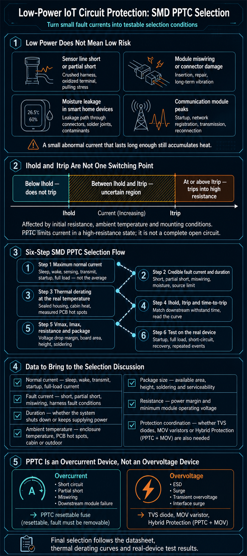
IoT circuit protection cannot be designed around average power consumption alone. Low power only means the normal operating current is small; it does not mean abnormal current is harmless. A shorted sensor line, incorrect module connection, moisture-related leakage, poor connector contact, or localized overload can keep a compact PCB, battery path, or communication module warm for a long period of time.
The challenge is greater because IoT devices are often installed remotely, inside sealed housings, in vehicle cabins, on walls, above ceilings, or inside equipment. When the fault is not an obvious hard short but a persistent low-level current fault, the issue may not be noticed immediately. The real maintenance cost appears later, after the battery drains, sensor accuracy drifts, the module resets, or heat marks are already visible on the board.
Engineer Lin encountered this kind of problem on a smart lock project. The prototypes ran normally on the lab bench, but after two weeks of outdoor testing, several units showed abnormal battery drain. After teardown, the team found moisture near a connector that created a low-level leakage path. It was not a major fault that burned the circuit immediately, but it was enough to warm a local area for an extended time and reduce both battery life and reliability.
This article turns these small-current fault conditions into verifiable selection criteria: normal load current, credible fault current, fault duration, ambient temperature, thermal derating, package limits, resistance, and real-device testing. When the application conditions are suitable, a PPTC resettable fuse can be one option for resettable overcurrent protection. However, suitability still needs to be confirmed against the datasheet, thermal derating curves, and actual testing.
Want to confirm the product scope first? Review Fuzetec Technology's PPTC resettable fuse product category, then return to this selection process to organize your design conditions.
For IoT circuit protection, the most commonly underestimated factor is fault duration. A brief peak may simply come from communication module startup or wireless transmission. A smaller but persistent abnormal current can still cause heat to accumulate in local copper traces, connectors, protection devices, or battery paths.
Protection design needs to ask a different set of questions:
If the protection device is a one-time fuse, a fault may require disassembly and replacement. If the fault is a removable and recoverable overcurrent scenario, the resettable behavior of a PPTC resettable fuse becomes worth evaluating. According to Fuzetec's PPTC fundamentals, a PPTC provides a conductive path in its normal state. When fault current heats the device, the material state changes, resistance rises, and current is limited. After the fault is removed and the device cools, it can return to its operating state.
This does not mean PPTC is suitable for every fault mode. It is suitable for overcurrent scenarios that need repeat protection and where the fault can be removed. If the fault condition cannot make the device enter an effective protection state, or if the system needs very precise electronic current limiting, the protection architecture should be reassessed.
Partial shorts are easy to overlook. They may not shut the power supply down immediately, and they may not make the device fail completely. They may simply cause one sensor power rail to draw extra current for a long time. For a small board, small battery, and sealed housing, that can already become a reliability problem.
Therefore, sensor protection is not only about adding a device at the interface. The design also needs to confirm whether the protection point can limit long-duration abnormal current when the sensor power line is shorted, partially shorted, or affected by moisture leakage. If product documents require Chinese-English terminology, these conditions can be organized as sensor protection validation items, including normal current, fault current, fault duration, and recovery behavior.
Assume Engineer Chen is working on a sensor harness in an automotive seat control module. Room-temperature functional tests all pass, but after the module is installed in the seat structure, the harness is pressed by a bracket at one corner. It does not create a hard short. It only causes intermittent contact abnormality when the seat moves. If the design considers only normal load current and does not define credible fault conditions, it becomes difficult during validation to determine whether the protection device can limit risk under this type of abnormal condition.
This type of abnormal condition conflicts easily with the idea of low power. The product normally consumes very little current, so the battery design and power path may have limited margin. When leakage persists, the problem may first appear as shorter battery life, then as unstable sensing or communication failure.
When selecting an SMD PPTC, using only sleep current as the normal current can cause nuisance trips during startup or transmission. On the other hand, choosing an oversized hold current to avoid nuisance trips can make a real low-current fault less likely to trigger protection. This is the most common selection tradeoff in low-power devices.
This behavior has two implications for IoT circuit protection. First, in the normal state, the device should maintain low impedance to avoid unnecessary impact on the protected circuit. Second, when abnormal overcurrent occurs, the device must enter a high-resistance state under suitable conditions to reduce the current seen by downstream circuitry.
For low-power devices, a common mistake is only confirming that Ihold is higher than average current. A more complete approach confirms that Ihold remains higher than the maximum normal current at the actual ambient temperature, while Itrip and time-to-trip match credible fault conditions.
Fuzetec PPTC technical information also notes that the current range between IH and IT is not fully predictable. The device may remain low resistance, or it may transition to high resistance. The result is affected by initial resistance, ambient temperature, and installation conditions. This is especially important for small-current faults because the fault may fall near this uncertain region.
Design teams should therefore confirm system behavior after protection:
The following process can help organize the data needed before selecting a PPTC for low-power equipment.
If Ihold is selected only from the average value, normal startup may be misidentified as a fault.
For each scenario, estimate or measure the possible current and how long the system continues supplying power. Even a small current can create a thermal issue if it persists long enough.
Fuzetec's PPTC selection guide lists thermal derating and environmental conditions as selection considerations. For IoT equipment, use measured PCB hot spots instead of room-temperature estimates only.
No single formula can replace testing across these three factors. When fault current is close to the uncertain region between Ihold and Itrip, real-device confirmation is required.
SMD package size affects more than whether the component fits. It also affects soldering, heat dissipation, copper area, distance to nearby components, and serviceability. On a high-density board, the component location can sometimes affect real behavior more than the component name.
If the ambient temperature is high, Fuzetec's High Temperature Series can also be reviewed. Suitability still needs to be confirmed through the actual datasheet and prototype testing.
PPTC can play an overcurrent limiting role in system protection, but it should not be treated as a substitute for TVS diodes or MOV varistors.
PPTC resettable fuses can be used when resettable overcurrent protection is needed and the fault can be removed. SMD PPTC devices are especially worth evaluating in high-density boards and miniaturized products. Final selection, however, cannot be based only on the name or package. It still needs to be confirmed through the datasheet, thermal derating curves, and real-device testing.
If your IoT device, sensor, smart home product, communication module, or automotive seat control board is evaluating low-power protection devices, first list the working voltage, maximum normal current, possible fault current, maximum ambient temperature, and package limits. Then check the candidate series datasheet and provide the organized conditions to the Fuzetec Technology team when samples or selection support are needed.
Fuzetec Technology, Complete Guide to Selecting PPTC Resettable Fuses
Fuzetec Technology, PPTC Resettable Fuse Product Category
Fuzetec Technology, SMD PPTC Product Category
Fuzetec Technology, Overvoltage Protection Product Category
Semiware, How PPTC Resettable Fuses Protect Electronic Circuits
The challenge is greater because IoT devices are often installed remotely, inside sealed housings, in vehicle cabins, on walls, above ceilings, or inside equipment. When the fault is not an obvious hard short but a persistent low-level current fault, the issue may not be noticed immediately. The real maintenance cost appears later, after the battery drains, sensor accuracy drifts, the module resets, or heat marks are already visible on the board.
Engineer Lin encountered this kind of problem on a smart lock project. The prototypes ran normally on the lab bench, but after two weeks of outdoor testing, several units showed abnormal battery drain. After teardown, the team found moisture near a connector that created a low-level leakage path. It was not a major fault that burned the circuit immediately, but it was enough to warm a local area for an extended time and reduce both battery life and reliability.
This article turns these small-current fault conditions into verifiable selection criteria: normal load current, credible fault current, fault duration, ambient temperature, thermal derating, package limits, resistance, and real-device testing. When the application conditions are suitable, a PPTC resettable fuse can be one option for resettable overcurrent protection. However, suitability still needs to be confirmed against the datasheet, thermal derating curves, and actual testing.
Want to confirm the product scope first? Review Fuzetec Technology's PPTC resettable fuse product category, then return to this selection process to organize your design conditions.
Key Takeaways
- Risks in IoT, sensor, smart home, and automotive seat modules do not come only from hard shorts. Persistent small-current faults can also create reliability issues.
- SMD PPTC devices are useful for board-level overcurrent protection when space is limited, but selection cannot be based only on package size or average sleep current.
- Hold current (Ihold), trip current (Itrip), time-to-trip, resistance, ambient temperature, and fault current must be checked together.
- The region between Ihold and Itrip is not an absolutely safe zone. According to Fuzetec PPTC technical information, behavior in this region is affected by initial resistance, ambient temperature, and installation conditions.
- If the risk is ESD, surge, or transient overvoltage, evaluate TVS diodes, MOV varistors, or hybrid protection (PPTC + MOV) separately. Do not rely on PPTC alone.
Why Low-Power IoT Circuit Protection Cannot Ignore Small-Current Faults
The main goals of low-power design are usually to extend battery life, reduce standby consumption, shrink the power module, and allow devices to remain deployed for long periods. Circuit protection, however, is not about average power consumption. It is about where current flows under abnormal conditions, how long it flows, how much heat it creates, and whether the system can recover safely.For IoT circuit protection, the most commonly underestimated factor is fault duration. A brief peak may simply come from communication module startup or wireless transmission. A smaller but persistent abnormal current can still cause heat to accumulate in local copper traces, connectors, protection devices, or battery paths.
Small normal operating current does not mean fault energy can be ignored
In early specifications, engineers often see average current, sleep current, or transmit current. These values help estimate battery life, but they are not enough to select a protection device.Protection design needs to ask a different set of questions:
- If the sensor power line is shorted, how much current can the power source deliver?
- If a communication module is connected incorrectly or fails internally, what limits the current?
- After the system detects an abnormal condition, does it shut down immediately or continue supplying power?
- What is the actual ambient temperature inside the small enclosure?
- Is the PPTC on the PCB placed near a power IC, MOSFET, inductor, or another heat source?
Remote and sealed deployments increase maintenance cost
IoT devices are not always monitored on site. Smart home products may be installed in door frames, walls, or ceilings. Industrial sensors may be distributed across equipment or pipelines. Automotive seat sensors may be hidden inside seat structures or near wiring harnesses.If the protection device is a one-time fuse, a fault may require disassembly and replacement. If the fault is a removable and recoverable overcurrent scenario, the resettable behavior of a PPTC resettable fuse becomes worth evaluating. According to Fuzetec's PPTC fundamentals, a PPTC provides a conductive path in its normal state. When fault current heats the device, the material state changes, resistance rises, and current is limited. After the fault is removed and the device cools, it can return to its operating state.
This does not mean PPTC is suitable for every fault mode. It is suitable for overcurrent scenarios that need repeat protection and where the fault can be removed. If the fault condition cannot make the device enter an effective protection state, or if the system needs very precise electronic current limiting, the protection architecture should be reassessed.
Common Small-Current Fault Scenarios in IoT Devices
Fault sources in IoT products are not limited to the main power input. Sensors, connectors, harnesses, batteries, communication modules, and enclosure environments can all create abnormal current in low-power devices.Short or partial short on a sensor power line
Sensors are often connected to the main board through harnesses or flat cables. If a harness is crushed, a terminal oxidizes, a connector is exposed to moisture, or assembly creates pulling stress, a short or partial short may occur.Partial shorts are easy to overlook. They may not shut the power supply down immediately, and they may not make the device fail completely. They may simply cause one sensor power rail to draw extra current for a long time. For a small board, small battery, and sealed housing, that can already become a reliability problem.
Therefore, sensor protection is not only about adding a device at the interface. The design also needs to confirm whether the protection point can limit long-duration abnormal current when the sensor power line is shorted, partially shorted, or affected by moisture leakage. If product documents require Chinese-English terminology, these conditions can be organized as sensor protection validation items, including normal current, fault current, fault duration, and recovery behavior.
Module insertion/removal, reverse connection, or crushed harnesses
Communication modules, seat sensor modules, and smart home control boards often connect to external harnesses or daughterboards. During assembly, repair, or long-term vibration, poor contact or local crushing can occur.Assume Engineer Chen is working on a sensor harness in an automotive seat control module. Room-temperature functional tests all pass, but after the module is installed in the seat structure, the harness is pressed by a bracket at one corner. It does not create a hard short. It only causes intermittent contact abnormality when the seat moves. If the design considers only normal load current and does not define credible fault conditions, it becomes difficult during validation to determine whether the protection device can limit risk under this type of abnormal condition.
Moisture leakage or contact abnormality in smart home devices
Smart locks, environmental sensors, window sensors, and lighting controllers may be installed near outdoor areas, kitchens, bathrooms, or semi-open spaces. Moisture does not always create an obvious short, but it can form a leakage path through connectors, solder joints, or contaminants.This type of abnormal condition conflicts easily with the idea of low power. The product normally consumes very little current, so the battery design and power path may have limited margin. When leakage persists, the problem may first appear as shorter battery life, then as unstable sensing or communication failure.
Startup, connection, or fault peaks in communication modules
A low-power IoT device does not draw low current at every instant. Wireless communication modules can create short-duration peaks during startup, connection, data transmission, or network search.When selecting an SMD PPTC, using only sleep current as the normal current can cause nuisance trips during startup or transmission. On the other hand, choosing an oversized hold current to avoid nuisance trips can make a real low-current fault less likely to trigger protection. This is the most common selection tradeoff in low-power devices.
How PPTC Resettable Fuses Protect Low-Power Devices
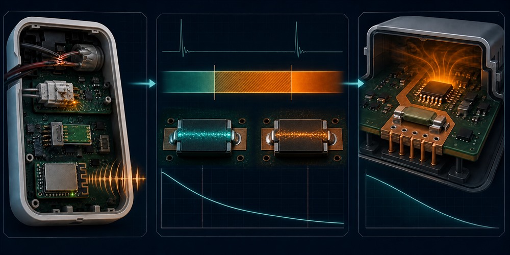
A PPTC resettable fuse is a resettable overcurrent protection device. According to Fuzetec technical articles, conductive particles are dispersed within the polymer structure of a PPTC material. In the normal state, they form conductive paths. When abnormal current causes heating, the material state changes, the conductive particles separate, and device resistance rises to limit current.This behavior has two implications for IoT circuit protection. First, in the normal state, the device should maintain low impedance to avoid unnecessary impact on the protected circuit. Second, when abnormal overcurrent occurs, the device must enter a high-resistance state under suitable conditions to reduce the current seen by downstream circuitry.
Ihold and Itrip are the core selection parameters
Hold current (Ihold) is the maximum current the device can carry at a specified temperature without tripping. Trip current (Itrip) is the minimum current required for the device to enter the protection state at a specified temperature. These two parameters cannot be evaluated separately.For low-power devices, a common mistake is only confirming that Ihold is higher than average current. A more complete approach confirms that Ihold remains higher than the maximum normal current at the actual ambient temperature, while Itrip and time-to-trip match credible fault conditions.
Fuzetec PPTC technical information also notes that the current range between IH and IT is not fully predictable. The device may remain low resistance, or it may transition to high resistance. The result is affected by initial resistance, ambient temperature, and installation conditions. This is especially important for small-current faults because the fault may fall near this uncertain region.
PPTC is not a complete open circuit
Technical articles and specifications should avoid describing PPTC as a complete open circuit. According to Fuzetec, in the fault state, a PPTC significantly increases resistance to limit current. This differs from a one-time fuse, which creates a permanent open circuit after melting.Design teams should therefore confirm system behavior after protection:
- Can the downstream module tolerate the residual current in the protection state?
- After the fault is removed, is automatic recovery allowed?
- If the fault occurs repeatedly, will firmware log or report the event?
- Can the user or service technician remove the external fault?
SMD PPTC Selection Process for IoT Circuit Protection: Start with Current, Temperature, and Package
SMD PPTC devices are well suited for high-density boards and space-constrained designs. Fuzetec's SMD PPTC product category lists multiple surface-mount series and provides product-level operating current, maximum voltage, features, temperature range, and specification downloads. During actual selection, always return to the corresponding product page and datasheet. Do not apply one series specification to every SMD PPTC.The following process can help organize the data needed before selecting a PPTC for low-power equipment.
Step 1: List the maximum normal current, not only average sleep current
Break normal current into operating states: sleep, wake, sensing, transmission, startup, full load, firmware update, and motor or actuator movement. Average current in IoT equipment may be low, but short peaks can be much higher than the average.If Ihold is selected only from the average value, normal startup may be misidentified as a fault.
Step 2: List credible fault current and duration
Fault conditions must be specific. Do not write only short circuit. List possible scenarios such as sensor power line short, harness partial short, module reverse connection, connector moisture, daughterboard failure, or incorrect external power connection.For each scenario, estimate or measure the possible current and how long the system continues supplying power. Even a small current can create a thermal issue if it persists long enough.
Step 3: Apply thermal derating using the actual temperature
Thermal derating is often missed in low-power equipment. Ambient temperature affects available hold current. A sealed housing, vehicle cabin, sunlight exposure, power IC, communication module, and nearby heat sources can all make the temperature around the PPTC higher than the original engineering assumption.Fuzetec's PPTC selection guide lists thermal derating and environmental conditions as selection considerations. For IoT equipment, use measured PCB hot spots instead of room-temperature estimates only.
Step 4: Confirm Ihold, Itrip, and time-to-trip
Ihold should be higher than the maximum normal current at the actual temperature. Itrip should be lower than the fault current range where protection is expected to intervene. Time-to-trip should be matched to the abnormal duration that downstream devices can tolerate.No single formula can replace testing across these three factors. When fault current is close to the uncertain region between Ihold and Itrip, real-device confirmation is required.
Step 5: Confirm Vmax, Imax, resistance, and package limits
Low-power devices can also be sensitive to voltage drop. PPTC resistance affects power margin, especially in battery-powered devices, low-voltage sensors, or communication module power paths.SMD package size affects more than whether the component fits. It also affects soldering, heat dissipation, copper area, distance to nearby components, and serviceability. On a high-density board, the component location can sometimes affect real behavior more than the component name.
Step 6: Test on the real device, not only the datasheet
The datasheet is the starting point for selection, not the conclusion. Low-power equipment should include at least the following tests:- Normal startup testing at room temperature and maximum ambient temperature
- Full-load and communication peak testing
- Sensor line short or partial-short testing
- PCB hot-spot measurement after the housing is sealed
- Recovery behavior after the fault is removed
- System function confirmation after repeated abnormal events
Low-Power Device PPTC Selection Checklist
The point of this checklist is not merely to fill in data. It is to help hardware, firmware, reliability, and purchasing teams discuss IoT circuit protection fault conditions using the same language. In one wireless sensor project, Engineer Wang initially provided only average power consumption and battery capacity. The supplier could not determine whether the protection device was appropriate. After the team added startup peak current, maximum internal housing temperature, sensor-line short conditions, and PCB layout location, the selection discussion changed from which part is smaller to which specification can pass real fault testing.| Item to Check | Why It Matters | Data to Provide |
| Normal current | Prevents nuisance tripping during normal operation | Sleep, wake, transmit, startup, and full-load current |
| Fault current | Determines whether the device can enter the protection state | Short, partial short, incorrect connection, and harness fault conditions |
| Duration | A small abnormal current can still heat up if it lasts long enough | Whether the system shuts down or continues supplying power after the fault |
| Ambient temperature | Affects Ihold and trip behavior | Internal housing temperature, PCB hot spots, vehicle cabin or outdoor conditions |
| Package size | IoT boards have limited space | Available board area, height, soldering, and serviceability conditions |
| Resistance | Low-voltage rails may be affected by voltage drop | Power margin and minimum operating voltage of the module |
| Protection coordination | PPTC is not an overvoltage protection device | Whether TVS diodes, MOV varistors, or Hybrid Protection (PPTC + MOV) are also needed |
Which Applications Should Evaluate SMD PPTC First?
SMD PPTC is not automatically suitable for every IoT device just because it is small. It should be evaluated first when board space is limited, resettable overcurrent protection is needed, and the fault condition can be removed or recovered.Smart home sensors and control boards
Door locks, window sensors, lighting control, air-quality sensors, and environmental monitoring nodes often have small PCBs, battery power, external connectors, and long standby requirements. If the risk comes from overcurrent on the sensor power line, connector, or low-voltage power path, evaluate whether an SMD PPTC meets the current, temperature, and package conditions.Remote monitoring nodes and industrial IoT sensors
Industrial IoT sensors may be deployed inside equipment, near pipelines, or in control cabinets. These locations are not always easy to service. If the abnormal condition is a removable overcurrent fault and the system can recover after the fault is cleared, PPTC resettable behavior can reduce the need to replace a one-time protection device.Communication modules and wireless module power paths
The current waveform of a communication module is usually more dynamic than that of a general sensor. During selection, pay special attention to peaks during startup, network registration, data transmission, and reconnection so normal communication behavior is not mistaken for a fault.Automotive seat sensors, control modules, and low-voltage peripherals
Automotive seat-related modules may face combined conditions from harness bending, mechanical compression, occupant sensing, heating, and control peripherals. If PPTC is used, cabin or in-seat temperature, harness fault conditions, and mounting location must be included in thermal derating and real-device testing.If the ambient temperature is high, Fuzetec's High Temperature Series can also be reviewed. Suitability still needs to be confirmed through the actual datasheet and prototype testing.
When PPTC Alone Is Not Enough
A common mistake in protection device selection is assigning different fault types to one device. PPTC is an overcurrent protection device, not a complete answer to every electrical risk.ESD, surge, and transient overvoltage need separate protection
If the product risk comes from ESD, lightning surge, transient overvoltage, or external interface surges, evaluate an overvoltage protection architecture. Fuzetec's Overvoltage Protection product category includes MOV varistors, TVS diodes, and Hybrid Protection (PPTC + MOV), which can be used for further review.PPTC can play an overcurrent limiting role in system protection, but it should not be treated as a substitute for TVS diodes or MOV varistors.
Other solutions may be needed for precise current limiting or fast electronic shutdown
Some low-power devices require a clearly defined current threshold, fast shutdown, fault reporting, or firmware control. These situations may require a protection IC, electronic switch, MOSFET power path, or another protection architecture. Whether PPTC is appropriate depends on the system's allowed response time, residual current, and recovery method.If fault current is below Itrip, recheck the protection design
If the credible fault current is too low, below Itrip, or in the uncertain region between Ihold and Itrip, do not assume the PPTC will trip quickly. The design may need to adjust the protection point, reassess Ihold and Itrip, change power current limiting, or add system-level detection.FAQ: IoT Circuit Protection and SMD PPTC
If an IoT device draws very little current, why does it still need overcurrent protection?
Because low power describes the normal operating state. It does not mean the fault state is risk-free. A shorted sensor line, moisture in a connector, incorrect module connection, or crushed harness can allow a small-current fault to persist for a long time. Protection design should confirm possible fault current, duration, and heat accumulation instead of looking only at average current.Is SMD PPTC suitable for every sensor power line?
Not necessarily. SMD PPTC is suitable for space-constrained scenarios that need resettable overcurrent protection, but the design still needs to confirm working voltage, maximum normal current, possible fault current, Ihold, Itrip, time-to-trip, resistance, thermal derating, and package conditions.Is it enough for Ihold to be higher than average operating current?
No. Ihold should be higher than the maximum normal current at the actual ambient temperature, not only higher than average sleep current. Low-power equipment can have short peaks during startup, transmission, or wake-up, and those peaks belong in the normal-condition definition.If a small-current fault is below Itrip, will the PPTC still operate?
Do not assume that it will. According to Fuzetec PPTC technical information, behavior between IH and IT cannot be fully determined and is affected by initial resistance, ambient temperature, and installation conditions. If fault current is below Itrip or near the uncertain region, confirm performance with real-device testing and adjust the protection architecture if needed.Can PPTC replace TVS diodes for ESD protection?
This is not recommended. PPTC is mainly used for overcurrent protection. ESD, surge, and transient overvoltage should be evaluated separately with TVS diodes, MOV varistors, or Hybrid Protection (PPTC + MOV). Different fault types require coordinated protection devices.What should be checked when selecting PPTC for automotive seat sensors or smart cockpit modules?
In addition to normal current and fault current, confirm cabin or in-seat temperature, harness bending or crushing conditions, module location, nearby heat sources, package height, vibration environment, and real-device test conditions. Do not judge suitability only from room-temperature Ihold.Conclusion: Turn Small-Current Faults into Testable Selection Conditions
The key to IoT circuit protection is not treating low-power products as low-risk products. It is turning each abnormal condition into testable electrical and thermal criteria. Normal current, fault current, duration, ambient temperature, package, resistance, and recovery behavior should all be organized before selection begins.PPTC resettable fuses can be used when resettable overcurrent protection is needed and the fault can be removed. SMD PPTC devices are especially worth evaluating in high-density boards and miniaturized products. Final selection, however, cannot be based only on the name or package. It still needs to be confirmed through the datasheet, thermal derating curves, and real-device testing.
If your IoT device, sensor, smart home product, communication module, or automotive seat control board is evaluating low-power protection devices, first list the working voltage, maximum normal current, possible fault current, maximum ambient temperature, and package limits. Then check the candidate series datasheet and provide the organized conditions to the Fuzetec Technology team when samples or selection support are needed.
Sources
Fuzetec Technology, PPTC FundamentalsFuzetec Technology, Complete Guide to Selecting PPTC Resettable Fuses
Fuzetec Technology, PPTC Resettable Fuse Product Category
Fuzetec Technology, SMD PPTC Product Category
Fuzetec Technology, Overvoltage Protection Product Category
Semiware, How PPTC Resettable Fuses Protect Electronic Circuits
Tag