Table of Contents
Resettable protection for unmanned equipment can limit fault current with a PPTC and avoid fuse replacement after the fault clears, power is removed, and the device cools. System recovery also needs controlled restart. [1]
Fuzetec Technical Team / Industrial Automation & IoT Application Engineer | EN | Published 2026-10-06 | Updated 2026-10-07The maintenance pain of unmanned scenarios
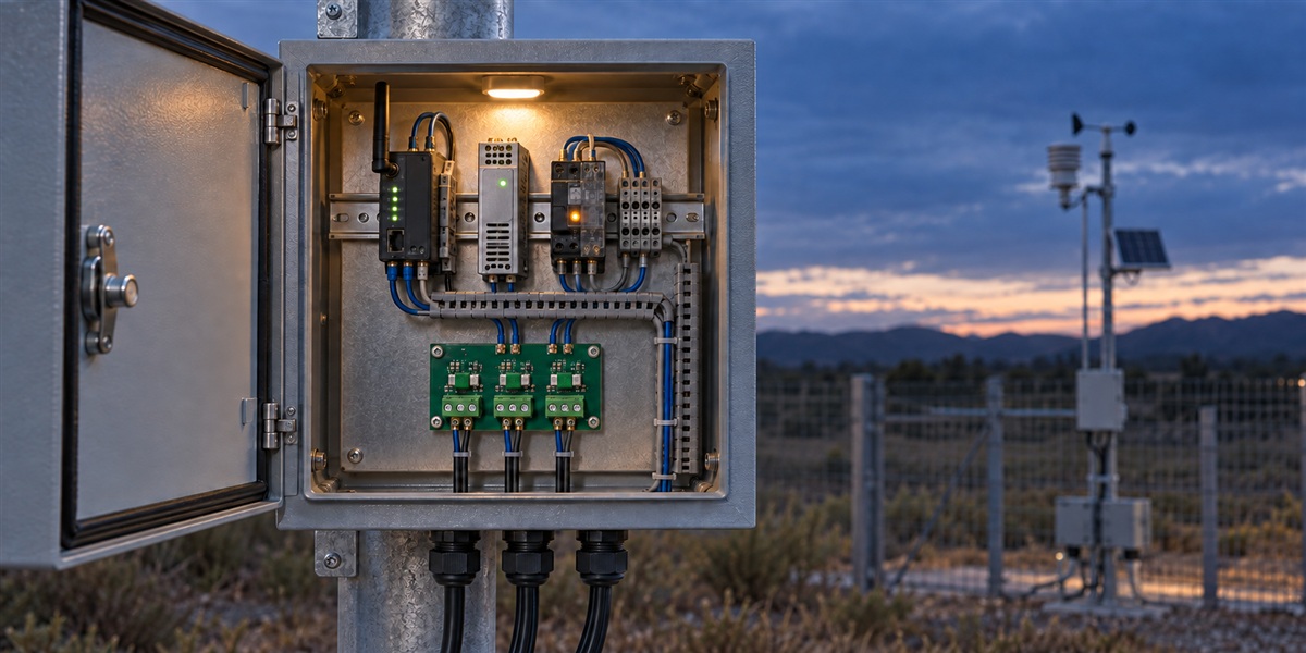
Resettable protection for unmanned equipment addresses a practical service problem. Consider an unattended monitoring cabinet that stops reporting overnight. A technician arrives, finds an open fuse on a sensor branch, and replaces it. The component costs little, but travel, access arrangements, troubleshooting, and missing measurements make the incident expensive. This is an illustrative scenario, not a documented customer case.This protection becomes useful when a temporary electrical fault would otherwise trigger a replacement visit. Examples include an intermittent peripheral overload or a short that clears after a connector is corrected. A permanently damaged cable still needs repair. Removing the replacement step cannot remove the underlying fault.
Start with the service objective: which branch may recover automatically, which must remain disabled, and which functions must stay available to report the event? A cabinet that loses its communications supply together with the faulty sensor cannot reliably request or execute a remote reset. Separate the recovery controller from the branch it controls, and examine unintended power paths through signal cables.
The commercial case should use your own service records. Compare avoided replacement visits and recoverable downtime with the added switching, monitoring, validation, and support costs. Do not count every historical outage as recoverable. Classify failures first, then estimate savings only for the subset that the proposed design can actually address.
The problem with one-time protection
A correctly selected one-time fuse provides fault-current interruption within its ratings, but it must be replaced after it operates. That behavior can be appropriate when a circuit should stay disconnected until someone investigates. In unattended equipment, however, replacement also extends an outage after a temporary fault has disappeared.A PPTC resettable fuse offers different behavior. Heating raises its resistance and limits current rather than creating the open circuit expected from a blown fuse. Residual current remains in the tripped state. [1] The protected circuit must tolerate that condition. As a design recommendation, use a separate means of disconnection wherever isolation is required.
Use the traditional fuse and PPTC comparison to frame the choice, then assess actual fault energy and interruption requirements. It is most attractive for suitable peripheral branches. It does not justify removing upstream protection, substituting a PPTC for every fuse, or allowing an actuator to restart merely because its supply has returned.
How resettable protection avoids manual work
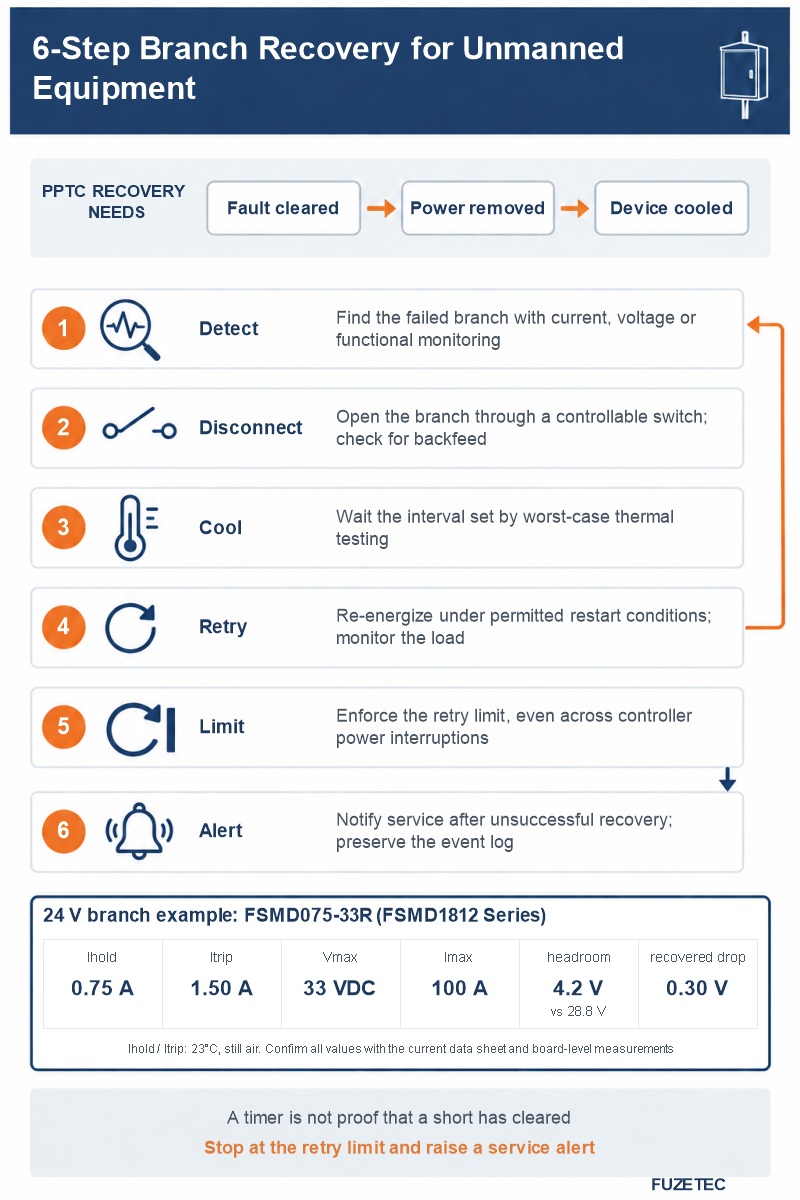
The resettable element avoids consumable replacement after a recoverable event. It does not, by itself, guarantee automatic system recovery. A PPTC can remain hot and resistive while power is applied. In many applications, the fault must clear, power must be removed, and the device must cool before normal operation resumes. Cooling and resistance recovery depend on the device and its thermal surroundings. [1]Design a recovery sequence around that limitation, assigning a measurable completion condition to each step:
- Detect the failed branch with current, voltage, or functional monitoring.
- Disconnect its supply through a controllable switch and check for backfeed.
- Cool for the interval established by worst-case thermal testing.
- Retry under permitted restart conditions and monitor the load response.
- Enforce the retry limit, including across controller power interruptions.
- Alert service personnel after unsuccessful recovery and preserve the event log.
Electronic fuses are another option when active fault reporting or selectable retry behavior is needed. The TI TPS2595 family, for example, lists a fault indication pin and auto-retry or latch-off options; check the particular variant before choosing its recovery behavior. [2] Compare the complete architecture: passive PPTC, controlled power switching, or an electronic protection solution. The useful result is a predictable recovery process, not simply a component labeled resettable.
Selection checklist for resettable protection for unmanned equipment
For an unattended installation, qualify the branch at its real operating conditions. The PPTC selection guide is a starting point; final decisions require the selected part's current data sheet and board-level measurements.First, establish the maximum continuous load, startup waveform, supply tolerance, prospective fault current, and local component temperature. Ambient room temperature is insufficient for a sealed cabinet beside a warm converter. Apply the manufacturer's thermal derating to hold current. Check startup duration against time-to-trip behavior rather than selecting from nominal amperes alone.
Second, match Vmax to the highest branch voltage, not its nominal value: after a PPTC trips, most of the supply voltage appears across its high resistance. [1] Check maximum fault current separately. A current-limited supply may deliver a fault waveform very different from a battery. Verify whether it trips the PPTC, enters its own hiccup mode, or leaves the load in an undesirable intermediate state. Protection coordination needs measured waveforms, not assumptions about which component operates first.
Third, evaluate resistance and voltage drop. Calculate branch drop using current multiplied by the applicable resistance, including specified post-trip resistance where relevant. Confirm that the sensor or modem can start at the lowest supply voltage with cable loss included. Also check the permitted temperature range, mounting conditions, and recognition requirements for the actual part.
Finally, test recovery with the enclosure hot, the fault persistent, and the communications link unavailable. Record branch current, load voltage, temperature, time to limit current, and time to restore operation. Define pass criteria before testing. Include repeated faults and power interruptions so the controller does not forget its retry limit whenever it reboots. These system tests do not imply a component-level guarantee.
For a 24 V branch example, use FSMD075-33R from the Fuzetec FSMD1812 Series data sheet B4. Its Vmax is 33 VDC; the table lists its electrical and mechanical values. [3] Schneider's M262 controller specifies a nominal 24 VDC supply and an allowed range of 20.4–28.8 VDC. This illustrates a supply-voltage requirement, not a recommendation to protect the entire PLC with this PPTC. [4]
Against that 28.8 V upper limit, 33 V provides 4.2 V of steady-state headroom. Confirm the actual supply specification, including ripple. Surges and reverse voltage from inductive-load turn-off can exceed the steady-state envelope; measure the voltage across the PPTC and coordinate suitable suppression. The 33 V rating alone does not guarantee protection. The 0.30 V estimate below applies to recovered resistance under the specified conditions, not the hot, tripped state.
| Parameter | Check for unattended operation | FSMD075-33R example [3] |
| Ihold (IH) | Derate the no-trip holding current for local temperature. | 0.75 A at 23°C, still air |
| Itrip (IT) | Check the trip-current threshold; it is not an instantaneous switching point. | 1.50 A at 23°C, still air |
| Vmax | Check maximum voltage across the device in the fault circuit. | 33 VDC |
| Imax | Compare prospective fault current with the rated withstand limit. | 100 A at Vmax |
| Pd | Evaluate thermal conditions in the tripped state; not normal load power. | 1.0 W typical at 23°C, still air |
| R1max | Budget post-trip voltage drop; this is not a reset-time guarantee. | 0.400 Ω at 23°C, measured 1 hour after tripping or 260°C / 20 s reflow |
| time-to-trip | Read the test current together with the maximum trip time. | 0.200 s maximum at 8 A, 23°C |
| Recovered voltage drop | Verify minimum load voltage and thermal derating; this is not tripped-state leakage. | 0.75 A × 0.400 Ω = 0.30 V, using R1max conditions |
| Thickness C | Check enclosure and board clearance. | 0.80–1.55 mm; FSMD075-R is 0.35–0.65 mm |
Application examples
For a remote environmental sensor, branch protection may reduce replacement visits after a recoverable peripheral overload. Keep the gateway powered independently enough to report the event and operate the branch switch. Verify that shared signal wiring cannot continue powering the sensor during the intended cooling interval. During the recovery test, capture the sensor supply at the connector, its startup current, and the first valid measurement after restart. A gateway reporting that it toggled a switch is not evidence that the sensor resumed useful operation.For PLC peripheral modules, protecting individual branches can help contain a fault, provided coordination testing confirms that the common supply remains available. A single PPTC at the cabinet input may leave every channel unavailable while it cools. Define which diagnostic messages survive the event and how the controller identifies the affected branch. Measure the common rail while intentionally faulting one peripheral branch. Check that neighboring modules neither reset nor lose their configuration. Repeat with the supply in its limiting mode, because branch selectivity can change when the source cannot deliver the same current as the laboratory supply.
For an unattended dispenser or small motor accessory, startup current and mechanical blockage require separate consideration. A cleared electrical overload does not establish that movement is safe. Where a jam persists or automatic movement is unacceptable, hold the affected function off and request service. Record motor current and the motion command separately during testing, and confirm that restoring electrical power does not bypass the commanded stop. These examples describe design possibilities, not verified Fuzetec customer deployments.
Across these applications, the protection design should be judged by completed recovery tests and fewer eligible service interventions. The phrase maintenance-free should describe no more than the intended absence of routine fuse replacement. Connectors, wiring, sensors, firmware, and mechanical parts still need maintenance appropriate to the installation.
FAQ
Does a PPTC reset automatically without disconnecting power?
Do not assume it will. The device needs conditions that let it cool and return toward low resistance. Many applications require power removal and fault clearance. Validate the complete circuit's reset sequence, including any backfeed paths. [1]Can a PPTC replace every one-time fuse in unmanned equipment?
No. Compare fault-current capability, voltage rating, trip behavior, residual current, and the required disconnected state. As a design recommendation, retain a one-time fuse or another interrupting device wherever the application requires that behavior. A resettable branch device may supplement that architecture.How long should the controller wait before retrying?
There is no universal interval. Establish it from the selected device's recovery information and testing at the board's worst thermal conditions. Set a retry limit and verify what happens when the fault remains present or the controller restarts.Does resettable protection make equipment maintenance-free?
No. It can avoid replacing a fuse after an eligible fault. Permanent electrical damage, contamination, loose connectors, and mechanical failures still need investigation. Track repeated trips so automatic recovery does not conceal a developing problem.Conclusion
Resettable protection for unmanned equipment can reduce visits caused by replaceable protection elements, provided the fault is recoverable and the system can safely restore power. Select the PPTC together with its branch switch, monitoring method, cooling interval, and retry policy. Validate persistent faults as carefully as successful recovery. That evidence makes the uptime benefit credible.CTA
Explore Fuzetec's PPTC resettable fuse portfolio and prepare your branch voltage, steady current, startup waveform, local temperature range, fault-current source, and intended restart behavior. Share these requirements with the Fuzetec team to discuss candidate devices and the measurements needed for your unmanned application.References
[1] Littelfuse: Fundamentals of Resettable Functionality in PPTC Devices[2] TI: TPS2595 product specifications
[3] Fuzetec: FSMD1812 data sheet B4, pp. 1–2
[4] Schneider: M262 DC supply characteristics
Tag