BMS Overcurrent Protection: Where PPTC Fits in Low-Voltage Branches and How to Select

Table of Contents
- What Is BMS Overcurrent Protection? Start by Understanding the Protection Layers
- How Does a PPTC Resettable Fuse Provide Overcurrent Protection?
- Where Should PPTC Be Placed in BMS Low-Voltage Branches?
- BMS Overcurrent Protection Selection Process
- How Do PPTC, OVP, and MOSFET Divide Protection Roles in BMS?
- How Can Fuzetec Help With BMS and Battery Module Protection Component Selection?
- FAQ: Common Questions About BMS Overcurrent Protection and PPTC Selection
- Conclusion: Layer First, Then Select Components
- Sources
BMS overcurrent protection is not finished just because a single protection component is placed inside a battery pack. PPTC resettable fuses are better suited for evaluation in low-voltage, resettable, and removable-fault BMS branches, such as low-voltage inputs on a control board, sensor or communication peripheral power, and some auxiliary battery-pack branches. Main battery outputs, high-voltage DC links, and high-energy fault paths still need a system-level protection architecture. A PPTC should not be treated as the only protection device.
The real problem is often not that engineers forgot protection entirely, but that they treat BMS overcurrent protection as a single location. A battery management system involves monitoring, communication, power paths, low-voltage supplies, and thermal conditions at the same time. Each layer has different fault energy, recovery needs, and validation requirements.Scenario: In April 2026, hardware engineer Alex was working on a 48 V energy storage module. The main circuit already had system-level protection, but the low-voltage auxiliary input on the BMS control board did not have independent current limiting. During the first prototype wiring test, a short circuit in a peripheral load caused localized heating on the control board. The issue was not that the main protection failed to act; it was that the low-voltage branch lacked suitable board-level overcurrent protection.
This article breaks BMS protection, or battery management system protection, into engineering layers that can be evaluated. It explains which low-voltage branches are reasonable candidates for PPTC resettable fuses, which locations should not be oversimplified, and what voltage, current, fault, and temperature data should be prepared before selection.
Key Takeaways
- BMS overcurrent protection is a layered architecture, not a single component selection. The main circuit, high-voltage paths, and low-voltage branches must be evaluated separately.
- A PPTC resettable fuse maintains low resistance in normal operation. When abnormal overcurrent causes heating, its resistance rises to limit current. After the fault is removed and the device cools, it can return to a low-resistance state.
- PPTCs are better suited for evaluation in low-voltage inputs on BMS control boards, sensor and communication peripheral power, some auxiliary battery-pack branches, and low-voltage branches where the fault can be removed.
- Before selection, confirm operating voltage, normal load current, peak current, possible fault current, Ihold, Itrip, time-to-trip, thermal derating, package, and real-system test conditions.
- Fuzetec can help engineering teams build a candidate list from PPTC Resettable Fuse, Overvoltage Protection, and Power MOSFET product categories, but final confirmation must still follow datasheets and actual testing.
What Is BMS Overcurrent Protection? Start by Understanding the Protection Layers
BMS stands for Battery Management System. According to Texas Instruments' battery management ICs page, battery management products include chargers, gauges, monitors, and protection ICs, and they are used in industrial, automotive, consumer electronics, HEV/EV, energy storage systems, and e-mobility applications.This means BMS protection / battery protection is not a single function. It usually includes voltage monitoring, current monitoring, temperature monitoring, cell balancing, communication, protection decisions, and power path control. Infineon's BMS application page also places battery management ICs, protection/monitoring ICs, current sensors, ESD/surge protection, and MOSFETs in the same application context, showing that BMS design requires multiple component types to work together.
Battery Monitoring and Protection ICs: Detecting a Fault Is Not the Same as Absorbing All Fault Energy
The role of a BMS IC or protector IC is usually related to monitoring, decision-making, communication, or control. These ICs can detect voltage, current, temperature, or status, but the components that actually absorb fault energy may be MOSFETs, fuses, contactors, peripheral components around protection ICs, or other system-level protection devices.Therefore, when an engineering team asks, "How should BMS overcurrent protection be designed?" the first step is not to directly select a PPTC, MOSFET, or fuse. The first step is to map the fault path: Where does the current come from? Which branch does it pass through? How much energy is present during the fault? Does the system need to recover after the fault is removed, or must it open permanently and be handled through a maintenance process?
Power Path Protection: Main Circuits Require a System Architecture Perspective
The main battery output, high-voltage DC link, charge/discharge main path, and high-energy short-circuit paths are system-level protection issues. These locations usually involve regulations, safety strategy, contactors, fuse protection, MOSFET power paths, thermal design, and full-system validation.A PPTC resettable fuse should not be described as a universal replacement for these high-energy paths. Fuzetec's PPTC fundamentals explain that a PPTC limits current by increasing resistance when fault heating occurs. It does not become an ideal circuit breaker. This difference is especially important in BMS main circuits because the fault energy may exceed the range that a typical board-level resettable device can withstand.
Low-Voltage Branch Protection: Where PPTC Has a Clearer Evaluation Window
A BMS system still includes many low-voltage, low-energy, or local branches, such as control board inputs, sensor supplies, communication peripherals, auxiliary power, display or indicator circuits, low-voltage control boards, and some auxiliary battery-pack branches. If a local short, wiring error, or peripheral load abnormality occurs in these positions, the engineering team may want to limit current and allow the branch to recover after the fault is removed.This is the context where a PPTC resettable fuse is more suitable for evaluation: low voltage, resettable behavior, removable faults, and operating current, fault current, and thermal conditions that can all fall within the device specifications and validated test range.
How Does a PPTC Resettable Fuse Provide Overcurrent Protection?
A PPTC resettable fuse is a resettable overcurrent protection device. According to Fuzetec's PPTC selection guide, a PPTC maintains low resistance in normal operation. When overcurrent heats the material, resistance increases significantly. After the abnormal current returns to normal and the device cools, it returns to a low-resistance state and can protect the circuit again.Fuzetec's PPTC fundamentals further explain that conductive particles are distributed within the polymer structure. When fault current causes heating, the material state changes, reducing conductive paths, increasing resistance, and limiting current.
Ihold, Itrip, and Thermal Derating Must Be Reviewed Together
During selection, first define hold current (Ihold) and trip current (Itrip). Ihold can be understood as the current the device can continuously carry under specified conditions without tripping. Itrip is the current condition that triggers the device to enter a high-resistance state.However, a BMS low-voltage branch is not a single laboratory test point. Battery modules, energy storage enclosures, and EV peripheral environments may contain local heat sources, so the temperature around the PPTC may be higher than room temperature. Fuzetec's selection guide lists thermal derating and reminds engineers to confirm selection under different ambient temperatures. In high-temperature environments, the High Temperature Series can also be evaluated against actual conditions.
Scenario: Mina is responsible for a BMS communication sub-board. During a 25°C bench test, she sees stable branch current and uses only room-temperature Ihold for initial selection. During thermal chamber testing, the area near the PPTC is affected by both a DC/DC converter and residual heat from the battery module, increasing the actual local temperature. The available hold current drops, and a selection that originally looked conservative becomes a nuisance-trip risk.
This is not simply a component quality issue. It is a sign that the selection conditions did not reflect the actual temperature.
A PPTC Is Not an Ideal Circuit Breaker
A PPTC limits current by increasing resistance. It does not completely open the circuit like an ideal switch. This point must be stated clearly in a BMS article because the fault energy in battery systems can be high.If a branch requires permanent disconnection, clear isolation, or involves a high-energy main path, the engineering team should not treat a PPTC as the only protection. A PPTC is better placed where the fault can be removed, the branch can recover, and the specifications and thermal conditions can be verified.
Where Should PPTC Be Placed in BMS Low-Voltage Branches?
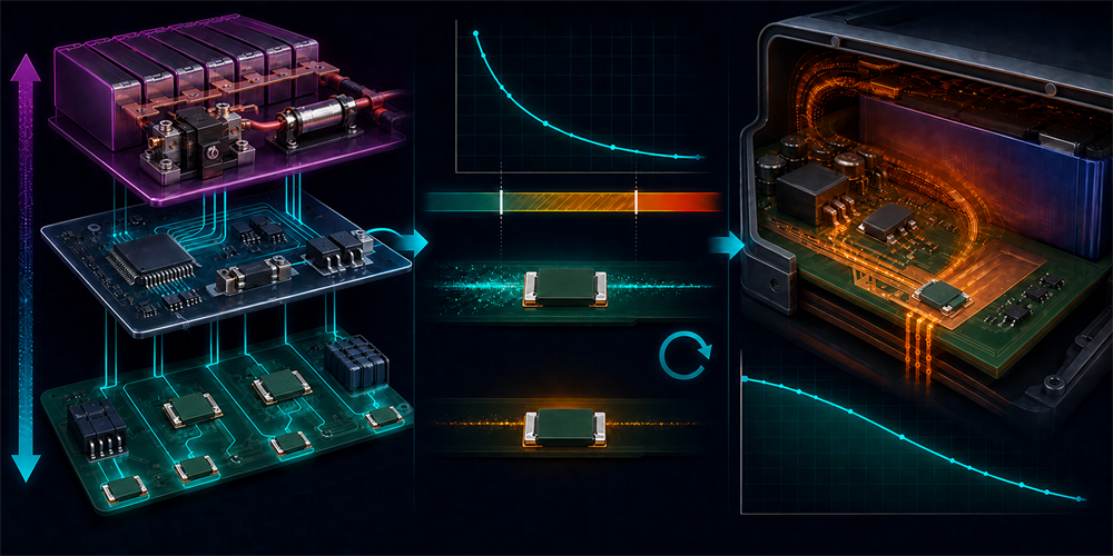
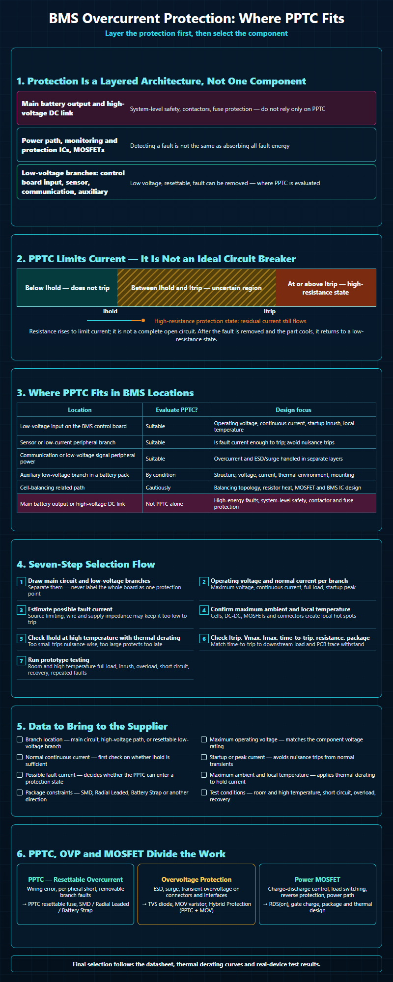
The following table can be used as a preliminary judgment tool. It does not replace a datasheet, nor does it guarantee suitability. Its purpose is to help engineers identify which locations are worth adding to a PPTC candidate list.
| BMS Location | Suitable for PPTC Evaluation? | Design Focus | Common Candidate Direction |
| Low-voltage input on the BMS control board | Suitable for evaluation | Operating voltage, continuous current, startup inrush, local temperature | SMD PPTC / Radial Leaded PPTC |
| Sensor or low-current peripheral branch | Suitable for evaluation | Whether fault current is sufficient to trip the PPTC; avoiding nuisance trips | SMD PPTC / Chip & Disc PPTC |
| Communication or low-voltage signal peripheral power | Suitable for evaluation | Overcurrent and ESD/surge protection must be handled in layers | SMD PPTC; evaluate OVP components separately when needed |
| Auxiliary low-voltage branch in a battery pack | Evaluate by condition | Structure, voltage, current, thermal environment, mounting method | Battery Strap / SMD / Radial, depending on structure |
| Cell-balancing related path | Evaluate cautiously | Balancing topology, resistor heat dissipation, MOSFET and BMS IC design | Confirm based on the actual circuit |
| Main battery output or high-voltage DC link | Should not rely only on PPTC | High-energy faults, system-level safety, contactor/fuse protection | Do not replace system-level protection with a general PPTC |
Low-Voltage Input on the BMS Control Board
A low-voltage input on the control board is a common board-level protection location. This branch usually supplies the BMS MCU, communication, sensing, or peripheral circuits. If wiring errors, downstream shorts, or external module faults occur, the engineering team may want to limit current and protect PCB traces and the upstream supply.Whether a PPTC is suitable depends on operating voltage, normal current, startup peak current, possible fault current, temperature near the PPTC, and package space. If PCB space is limited, the SMD PPTC product category can be reviewed first, but the selection still needs to return to the datasheet and actual testing.
Branch data not organized yet? First list the operating voltage, maximum continuous current, startup peak current, fault current, and maximum temperature for each low-voltage branch, then use product search to build a candidate part list.
Sensor, Communication, and Low-Voltage Peripheral Power
A BMS may connect to temperature sensors, current-sensing peripherals, communication isolation, or other low-voltage modules. Fault current in these branches may not be large, but a local short can still pull down the supply, heat the PCB, or cause upstream protection to trip unexpectedly.PPTC can be evaluated for local current limiting, but two points matter. First, the fault current must be high enough to make the PPTC enter a protection state within a reasonable time. Second, normal operation and short peak current must not be too close to Itrip, or high temperature and batch-to-batch resistance variation may cause nuisance trips.
If these branches also face ESD, surge, or transient voltage, a PPTC cannot replace TVS diodes, MOV varistors, or other overvoltage protection. Overcurrent and overvoltage are different faults and require layered design.
Battery-Pack Auxiliary Branches and Battery Strap
Fuzetec's Battery Strap page lists Strap Series battery PPTC resettable fuses, with applications including rechargeable battery packs, lithium cells, and battery packs. This makes Battery Strap a product direction worth evaluating in battery-pack contexts.Therefore, when discussing battery-pack overcurrent protection, first confirm whether the path is main-circuit protection, auxiliary-branch protection, or local current limiting on the BMS PCB.
However, "battery pack" is not a single condition. Different battery packs have different voltages, branch currents, mounting methods, cooling conditions, and fault energy. Battery Strap can be included as a candidate, but it should not be described as a replacement for main protection in all EV or ESS battery packs.
Locations That Should Not Be Simplified to PPTC
Main battery outputs, high-voltage DC links, charge/discharge main paths, and high-energy faults around contactors should not be covered with a simple statement such as "add a PPTC." These positions require system safety strategy, protection coordination, thermal design, power component selection, and full-system testing.If you are designing these paths, place PPTC back into the role of a branch-protection candidate rather than treating it as the main protection answer. If the design involves switching or a power path, the Power MOSFET product category and related thermal, RDS(on), and gate charge conditions should also be evaluated.
BMS Overcurrent Protection Selection Process
Before selecting a PPTC, organize the BMS low-voltage branch data into one table. This is more reliable than directly searching for part numbers, and it allows suppliers to judge candidate directions more quickly.Step 1: Draw the Main Circuit and Low-Voltage Branches First
Separate the main battery path, charge/discharge path, BMS control board supply, sensing branches, communication branches, auxiliary power, and other peripherals. Do not label only "BMS protection" on one diagram, because that can easily mix the main circuit with low-voltage branches.Step 2: Mark the Operating Voltage and Normal Current of Each Branch
Fuzetec's PPTC selection guide lists operating voltage and hold current as selection conditions. For BMS low-voltage branches, at minimum, identify maximum operating voltage, normal continuous current, full-load current, and startup peak current.Step 3: Estimate Possible Fault Current
For a PPTC to work during a fault, the fault current and thermal conditions must be sufficient to make the device enter a protection state. If the upstream supply already has current limiting, or if wiring resistance and supply impedance make fault current too low, the PPTC may not trip as expected. This must be confirmed through circuit analysis and prototype testing.Step 4: Confirm Maximum Ambient Temperature and Local Temperature
A BMS board does not necessarily operate at room temperature. EV, energy storage, and battery module housings, cells, DC/DC converters, MOSFETs, inductors, and connectors can all create local temperature rise. PPTC selection should use the actual temperature near the device, not just the laboratory ambient temperature.Step 5: Use Thermal Derating to Check Ihold at High Temperature
Thermal derating affects available hold current. If selection uses only room-temperature Ihold, nuisance trips may occur under high-temperature full load. Conversely, if Ihold is set too high to avoid nuisance trips, true-fault protection may become insufficiently sensitive.Step 6: Check Itrip, Vmax, Imax, Time-to-Trip, Resistance, and Package
Fuzetec's selection guide lists trip current, maximum voltage, maximum current, trip time, environmental conditions, and package as factors. BMS low-voltage branches should also be checked one by one, especially whether time-to-trip matches the tolerance of the downstream load and PCB traces.Step 7: Run Prototype Testing
The final step is real-system testing. Recommended tests include room-temperature full load, high-temperature full load, startup peak, overload, short circuit, recovery after fault removal, and condition checks after repeated faults. These tests cannot be replaced by an article or preliminary table.Scenario: Ravi's EV auxiliary power board used one shared protection point for the low-voltage communication branch and sensing branch in the first design. During short-circuit testing, an abnormal communication branch pulled down the sensing supply and caused unstable BMS reporting. In the second design, the team separated the branches first, then confirmed Ihold, Itrip, and local temperature for each branch. Only then was the issue clearly located. This case reminds us that the protection-point location is just as important as the part number.
How Do PPTC, OVP, and MOSFET Divide Protection Roles in BMS?
A BMS protection architecture should be viewed as a coordinated design, not a component list. PPTC, overvoltage protection, and Power MOSFET may all appear in the same system, but they solve different problems.PPTC: Resettable Overcurrent Limiting
The core value of a PPTC resettable fuse is providing resettable overcurrent limiting under suitable conditions. For BMS low-voltage branches, this is especially meaningful for wiring errors, peripheral shorts, or removable faults.The resettable characteristic of a PPTC is not a reason to skip testing. Resettable means it can return to a low-resistance state after the fault is removed and the device cools, but every application still needs to confirm fault energy, temperature, time, and system safety requirements.
Overvoltage Protection: Surge, ESD, and Transient Voltage
Fuzetec's Overvoltage Protection product category includes MOV varistors, TVS diodes, and Hybrid Protection (PPTC+MOV). These categories are commonly used when discussing surge, ESD, or transient voltage protection.In BMS low-voltage communication, external connectors, or sensing interfaces, overcurrent and overvoltage may exist at the same time. However, PPTC and TVS/MOV components have different functions and cannot replace one another. Selection still depends on waveform, voltage, energy, port location, and datasheet requirements.
Power MOSFET: Switching, Power Path, and Thermal Design
If a BMS design involves charge/discharge control, low-voltage load switching, reverse-connection protection, or a power path, the RDS(on), gate charge, package, and thermal performance of the Power MOSFET will affect overall behavior. Fuzetec's Power MOSFET product category currently lists Si MOSFET.A MOSFET can participate in protection control, but it is not a standalone answer either. If fault conditions exceed the device safe operating area, other protection strategies still need to be coordinated.
How Can Fuzetec Help With BMS and Battery Module Protection Component Selection?
Fuzetec Technology Co., Ltd. was founded in 1999. According to Fuzetec's company profile, the company is positioned as a protection component designer and manufacturer, and it mentions independently developed polymer positive temperature coefficient formula technology for PTC/PPTC resettable fuse products. Its product categories include PPTC Resettable Fuse, Overvoltage Protection, and Power MOSFET.For BMS, energy storage, EV, and battery module teams, a more practical way to collaborate on EV protection components or battery module protection components is not to ask, "Which single part can protect the whole system?" Instead, provide specific branch data so the protection component candidates are closer to real conditions. If the application belongs to ESS or a large battery cabinet, energy storage system protection components should also be separated into main-circuit, high-voltage path, and low-voltage branch candidates for discussion.
Data Checklist to Provide to the Supplier
| Data | Why It Is Needed |
| Branch location | Identifies whether it is a main circuit, high-voltage path, or low-voltage resettable branch |
| Maximum operating voltage | Confirms whether the voltage condition matches the component rating |
| Normal continuous current | Provides the first check for whether Ihold is sufficient |
| Startup or peak current | Helps avoid nuisance trips caused by normal transient current |
| Possible fault current | Determines whether the PPTC can enter a protection state |
| Maximum ambient and local temperature | Checks available hold current at high temperature through thermal derating |
| Package constraints | Determines whether SMD, Radial, Battery Strap, or another direction is appropriate |
| Test conditions | Confirms room-temperature, high-temperature, short-circuit, overload, and recovery behavior |
If your design has already organized the data above, you can contact Fuzetec and provide the circuit conditions to discuss whether PPTC, Overvoltage Protection, or Power MOSFET categories should be included as candidates.
FAQ: Common Questions About BMS Overcurrent Protection and PPTC Selection
Can PPTC replace the main BMS fuse or contactor?
No. That would oversimplify the design. PPTC is suitable for evaluation in low-voltage, resettable branches where the fault can be removed. Main battery outputs, high-voltage DC links, and high-energy fault paths should return to a system-level protection architecture. PPTC should not simply replace the main fuse, contactor, or other safety design.Why are low-voltage BMS branches suitable for resettable protection?
Common issues in low-voltage branches include peripheral shorts, wiring errors, and abnormal sensor or communication modules. If the branch should recover after the fault is removed, and if voltage, current, fault energy, and temperature conditions match the component specifications, a PPTC resettable fuse can be included as a candidate.Does a battery-pack PPTC always need to be Battery Strap?
Not necessarily. Battery Strap is suitable for evaluation in specific battery-pack structures and application conditions, but low-voltage branches on a BMS PCB may also use SMD PPTC or other packages. Selection depends on mounting method, operating voltage, current, thermal environment, and datasheet requirements.What should be considered when placing PPTC near a high-temperature battery module?
Thermal derating matters. Ambient temperature affects available hold current, and the local temperature around the PPTC may be higher than external temperature. Selection should confirm maximum ambient temperature, measured PCB temperature, nearby heat sources, and real-system full-load conditions.What is the difference between PPTC and TVS/MOV in BMS protection?
PPTC is mainly used for overcurrent protection. TVS diodes, MOV varistors, and Hybrid Protection (PPTC+MOV) belong to overvoltage, surge, or transient voltage protection contexts. They address different faults and should be designed in layers according to port, waveform, voltage, current, and energy conditions.What data should be provided to a supplier for selection support?
At minimum, provide branch location, operating voltage, normal current, peak current, possible fault current, maximum ambient temperature, local temperature around the PPTC, package constraints, and test conditions. The closer the data is to actual use conditions, the better the candidate component range can be narrowed.Conclusion: Layer First, Then Select Components
The real starting point for BMS battery management system overcurrent protection is not the part number. It is the protection layer. The main circuit, high-voltage path, low-voltage input on the control board, sensing branch, communication branch, and battery-pack auxiliary branch all face different fault energy and recovery requirements.The reasonable role for a PPTC resettable fuse is a low-voltage branch where the fault can be removed, recovery is useful, and specifications can be verified. Under suitable conditions, it can provide overcurrent limiting, but it should not be described as the only answer for the entire BMS overcurrent protection architecture.
The next step is practical: list the voltage, normal current, peak current, fault current, and maximum temperature of each branch, then build a candidate list based on Ihold, Itrip, time-to-trip, thermal derating, and package. If you need support comparing PPTC, Overvoltage Protection, or Power MOSFET categories, contact Fuzetec to discuss the actual circuit conditions.
Ready to start selection? Bring your branch data and review the PPTC Resettable Fuse product category, or contact us with your BMS, EV, ESS, and battery module application conditions.
Sources
Fuzetec Company Profile: https://www.fuzetec.com/en/about/company-profileFuzetec PPTC Resettable Fuse Product Category: https://www.fuzetec.com/en/product-group/pptc-resettable-fuse
Fuzetec PPTC Selection Guide: https://www.fuzetec.com/en/news-detail/pptc-resettable-fuse-selection-guide
Fuzetec PPTC Fundamentals: https://www.fuzetec.com/en/news-detail/pptc-resettable-fuse-fundamentals
Fuzetec Battery Strap: https://www.fuzetec.com/en/product-lists/strap-series
Fuzetec Overvoltage Protection: https://www.fuzetec.com/en/product-group/overvoltage-protection
Fuzetec Power MOSFET: https://www.fuzetec.com/en/product-group/power-mosfet
Texas Instruments Battery Management ICs: https://www.ti.com/product-category/battery-management-ics/overview.html
Infineon Battery Management Systems: https://www.infineon.com/cms/en/applications/solutions/battery-management-system/
Tag