PTC Fuse Selection: Matching Resettable Overcurrent Protection to Your Circuit's Real Operating Conditions

Table of Contents
A PTC (Positive Temperature Coefficient) fuse is a resettable overcurrent protection device that increases its resistance sharply when current or temperature exceeds a defined threshold, interrupting current flow without requiring physical replacement the way a traditional fuse does. Selecting the right PTC fuse for a circuit depends on matching several interrelated electrical parameters — hold current, trip current, maximum voltage, and time-to-trip behavior — to the actual operating and fault conditions of the application, rather than choosing based on a single rating in isolation.
A PTC fuse is constructed from a polymer material embedded with conductive particles, forming a network of conductive paths through the material at normal operating temperature. When current flow or ambient temperature raises the device's internal temperature past a critical point, the polymer expands, breaking the conductive particle network and causing resistance to increase sharply, which in turn limits current flow. Once the fault condition is removed and the device cools, the polymer contracts and conductivity is restored, allowing the circuit to resume normal operation without manual intervention.
 Hold current is typically the starting point for PTC fuse selection, since choosing a device with too low a hold current relative to the circuit's normal operating current results in nuisance tripping during legitimate operation, while too high a hold current fails to provide meaningful protection against moderate overcurrent conditions. Engineers should select hold current based on the maximum normal operating current the circuit will draw, including realistic margin for temperature variation and inrush current at power-up, rather than the nominal steady-state current alone.
PTC fuse hold current ratings are specified at a particular ambient temperature, typically 25°C, but actual device performance shifts meaningfully as ambient temperature changes, since the device's trip behavior is fundamentally temperature-dependent. A device operating in a higher-temperature enclosure will trip at a lower current than its rated hold current suggests, which is a common and consequential oversight in PTC fuse selection for enclosed or high-ambient-temperature applications.
Hold current is typically the starting point for PTC fuse selection, since choosing a device with too low a hold current relative to the circuit's normal operating current results in nuisance tripping during legitimate operation, while too high a hold current fails to provide meaningful protection against moderate overcurrent conditions. Engineers should select hold current based on the maximum normal operating current the circuit will draw, including realistic margin for temperature variation and inrush current at power-up, rather than the nominal steady-state current alone.
PTC fuse hold current ratings are specified at a particular ambient temperature, typically 25°C, but actual device performance shifts meaningfully as ambient temperature changes, since the device's trip behavior is fundamentally temperature-dependent. A device operating in a higher-temperature enclosure will trip at a lower current than its rated hold current suggests, which is a common and consequential oversight in PTC fuse selection for enclosed or high-ambient-temperature applications.
After determining the mounting method, browse the PPTC resettable fuse product series to further narrow down the options by radial-leaded, SMD, or chip form factor. Unlike a simple on/off threshold, PTC fuse trip time varies continuously with the severity of the overcurrent condition — a fault current only slightly above the trip threshold takes considerably longer to trigger tripping than a severe short-circuit condition. Engineers should review the manufacturer's time-to-trip curve for the specific device under consideration to confirm the response speed at the actual fault current levels relevant to their application, rather than assuming trip time is a fixed, single value. Because PTC fuse trip behavior is temperature-dependent, board layout choices around the device meaningfully affect its real-world performance. Placing heat-generating components too close to a PTC fuse can cause it to trip prematurely due to ambient heating rather than an actual overcurrent condition, while poor thermal dissipation around the device can slow its recovery time after tripping, occasionally leading engineers to mistakenly suspect a defective component rather than a layout-driven thermal issue.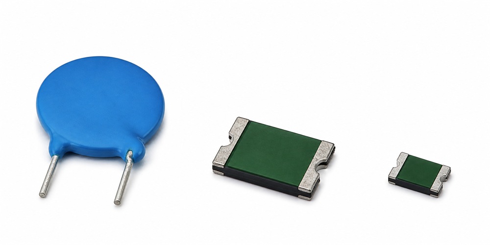
As portable electronics and battery-powered devices continue to demand compact, resettable overcurrent protection, PTC fuses remain a practical solution when selected with careful attention to the full range of real-world operating conditions rather than datasheet ratings alone. Involving component suppliers early in the design process further reduces the risk of costly late-stage redesigns once a product is already close to production.
Ultimately, treating PTC fuse selection as an engineering decision worthy of the same rigor applied to other critical circuit components — rather than a simple catalog lookup — is what separates designs that perform reliably in the field from those that generate recurring nuisance-trip complaints after launch.
To learn more about how pptc works to protect the device , see How PPTC Resettable Fuses Work
| Parameter | What It Defines |
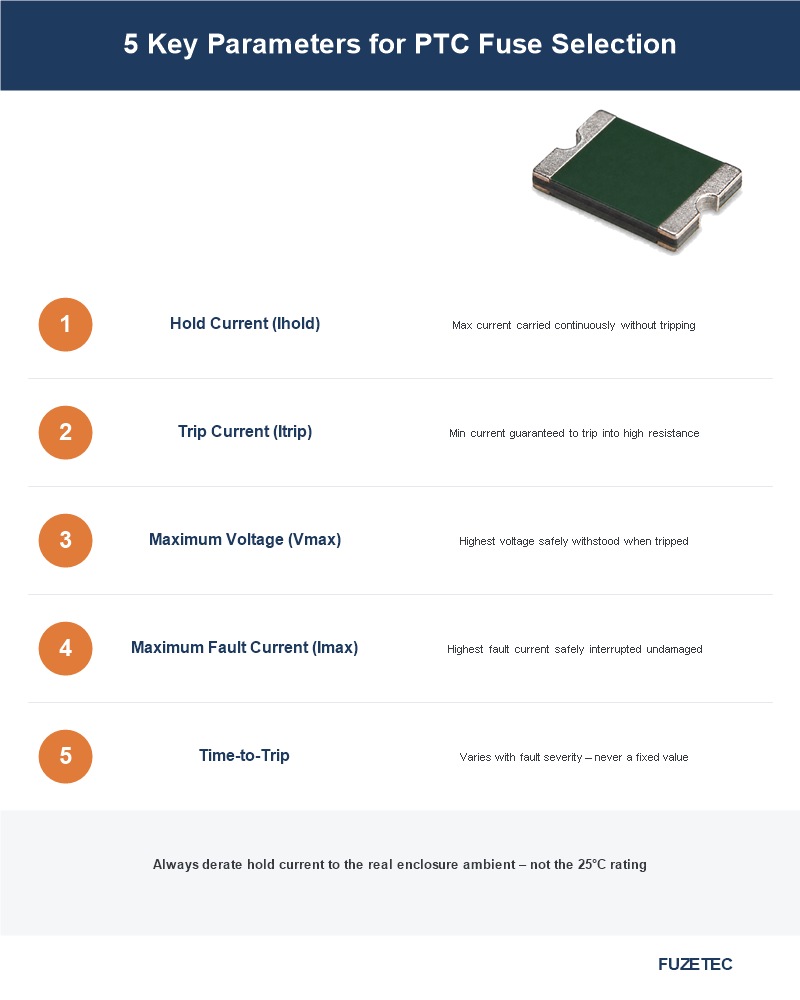
| Hold current (Ihold) | The maximum current the device carries continuously without tripping, at a specified ambient temperature |
| Trip current (Itrip) | The minimum current at which the device is guaranteed to trip into its high-resistance state |
| Maximum voltage (Vmax) | The highest voltage the device can safely withstand while in its tripped, high-resistance state |
| Maximum fault current (Imax) | The highest fault current the device can safely interrupt without damage |
| Time-to-trip | How quickly the device responds at a given overcurrent level, which varies with the severity of the fault |
Hold current is typically the starting point for PTC fuse selection, since choosing a device with too low a hold current relative to the circuit's normal operating current results in nuisance tripping during legitimate operation, while too high a hold current fails to provide meaningful protection against moderate overcurrent conditions. Engineers should select hold current based on the maximum normal operating current the circuit will draw, including realistic margin for temperature variation and inrush current at power-up, rather than the nominal steady-state current alone.
PTC fuse hold current ratings are specified at a particular ambient temperature, typically 25°C, but actual device performance shifts meaningfully as ambient temperature changes, since the device's trip behavior is fundamentally temperature-dependent. A device operating in a higher-temperature enclosure will trip at a lower current than its rated hold current suggests, which is a common and consequential oversight in PTC fuse selection for enclosed or high-ambient-temperature applications.
- Always derate hold current based on the actual maximum ambient temperature inside the enclosure, not the room temperature rating alone
- Request manufacturer derating curves showing hold current versus ambient temperature for the specific device under consideration
- Account for self-heating from adjacent components when estimating actual operating temperature around the PTC device
- Battery pack protection in portable electronics and battery packs, guarding against short-circuit and overcurrent conditions
- USB port and peripheral interface protection against overcurrent from connected devices
- Motor and actuator circuit protection where resettable operation avoids the need for physical fuse replacement
- Telecommunications equipment protection against line surge and fault conditions
- Choose PTC fuses when automatic reset after fault clearance is operationally important
- Choose traditional fuses when a precise, non-resettable trip characteristic is required for safety-critical circuit isolation
- Consider the physical accessibility of the protected circuit when weighing resettable versus one-time protection
Engineers can also explore the differences between traditional fuses and PPTC resettable fuses, and then select the appropriate solution based on reset requirements and safety characteristics.
PTC fuses are available in radial leaded, surface-mount, and chip form factors, and form factor selection depends on board space constraints, assembly process compatibility, and the thermal characteristics of each package type. Surface-mount devices generally offer better dimensional consistency for automated assembly, while leaded devices remain common in applications with more generous board space or where through-hole assembly is already standard.
| Form Factor | Typical Best Fit |
| Radial leaded | Through-hole assembly, applications with available board space |
| Surface-mount (SMD) | Space-constrained designs, automated pick-and-place assembly |
| Chip PTC | Highly compact designs such as portable electronics and wearables |
After determining the mounting method, browse the PPTC resettable fuse product series to further narrow down the options by radial-leaded, SMD, or chip form factor. Unlike a simple on/off threshold, PTC fuse trip time varies continuously with the severity of the overcurrent condition — a fault current only slightly above the trip threshold takes considerably longer to trigger tripping than a severe short-circuit condition. Engineers should review the manufacturer's time-to-trip curve for the specific device under consideration to confirm the response speed at the actual fault current levels relevant to their application, rather than assuming trip time is a fixed, single value. Because PTC fuse trip behavior is temperature-dependent, board layout choices around the device meaningfully affect its real-world performance. Placing heat-generating components too close to a PTC fuse can cause it to trip prematurely due to ambient heating rather than an actual overcurrent condition, while poor thermal dissipation around the device can slow its recovery time after tripping, occasionally leading engineers to mistakenly suspect a defective component rather than a layout-driven thermal issue.
- Avoid placing high-heat-dissipation components in close proximity to PTC fuses on the board layout
- Provide adequate copper pour or thermal relief around the device to support proper heat dissipation during normal operation
- Consider airflow and enclosure ventilation when the PTC fuse is located in a sealed or poorly ventilated housing
- Review manufacturer data on parameter drift after repeated trip cycles for applications with frequent expected tripping
- Build in margin on hold current rating for high-cycle applications rather than selecting the minimum adequate rating when new
- Consider periodic functional verification for safety-critical applications where PTC fuse degradation could go unnoticed
- Selecting hold current based on room-temperature ratings without derating for actual enclosure ambient temperature
- Overlooking inrush current at power-up, causing nuisance tripping during normal startup conditions
- Choosing maximum voltage rating without margin above the circuit's actual operating voltage
- Failing to verify maximum fault current rating against the worst-case fault current the circuit could realistically experience
- Share the actual expected operating current range, including realistic worst-case scenarios, with the supplier's application engineering team
- Request derating curves and time-to-trip data specific to the device under consideration, not generic category data
- Discuss enclosure thermal conditions and board layout constraints that could affect real-world performance
- Confirm availability and lead time for the selected device family before finalizing a design around it
- Full datasheet including hold current, trip current, maximum voltage, and maximum fault current ratings
- Temperature derating curves showing hold current across the expected ambient temperature range
- Time-to-trip curves at multiple overcurrent levels relevant to the application's expected fault scenarios
- Cycle life and parameter drift data for applications expecting frequent tripping over the product's service life
As portable electronics and battery-powered devices continue to demand compact, resettable overcurrent protection, PTC fuses remain a practical solution when selected with careful attention to the full range of real-world operating conditions rather than datasheet ratings alone. Involving component suppliers early in the design process further reduces the risk of costly late-stage redesigns once a product is already close to production.
Ultimately, treating PTC fuse selection as an engineering decision worthy of the same rigor applied to other critical circuit components — rather than a simple catalog lookup — is what separates designs that perform reliably in the field from those that generate recurring nuisance-trip complaints after launch.
PTC Resettable Fuse Selection & Application - FAQ
What does 'resettable' mean for a PTC fuse?
Once the fault condition clears and the device fully cools down, it automatically returns to a low-resistance state, restoring normal circuit operation without any replacement needed at all.
Why does ambient temperature affect PTC fuse selection?
Trip behavior is temperature-dependent, so a device can trip at a lower current than its rated hold current in a higher-temperature enclosure.
Should I choose hold current based on nominal or peak operating current?
Hold current selection should account for realistic peak conditions, including inrush current at power-up, not just nominal steady-state current.
Can a PTC fuse replace a traditional fuse in every application?
Not always — traditional fuses may be preferred where a precise, non-resettable trip is required for genuinely safety-critical circuit isolation.
Does board layout affect PTC fuse performance?
Yes — nearby heat-generating components and enclosure ventilation can meaningfully affect actual trip and recovery behavior in real-world use.
What should I test before finalizing a PTC fuse selection?
Test the selected device under actual ambient temperature, inrush current, and worst-case fault conditions rather than relying on datasheet values alone.
Does a PTC fuse's performance change after repeated tripping?
Yes — repeated trip cycles can gradually shift hold and trip current slightly over time, so high-cycle applications should include extra margin.
Which form factor should I choose for a space-constrained design?
Surface-mount or chip PTC devices are generally best suited to compact designs and automated assembly processes.
What documentation should I request before finalizing a PTC fuse choice?
Request full datasheets, temperature derating curves, and time-to-trip data specific to the actual device being considered, along with cycle life data where relevant.
Tag