Table of Contents
- Direct Answer: When an Industrial Control Board Fuse Keeps Tripping, Start With 5 Trip Patterns
- Industrial Control Board Fuse Keeps Tripping: How to Tell Overload, Short Circuit, Inrush, and Selection Error Apart
- Why Does a PPTC Resettable Fuse Trip?
- Step 1: Rule Out Short Circuits First, and Do Not Repeatedly Power Up for Testing
- Step 2: Confirm Whether the Cause Is Overload or a Load Change
- Step 3: Check Whether the PPTC Selection Is Too Close to the Boundary
- Step 4: Check Thermal Derating and Control Cabinet Temperature
- Step 5: Recheck PPTC Suitability With a Selection Data Checklist
- When Is a PPTC Suitable, and When Should It Be Re-Evaluated?
- FAQ: Industrial Control Board Fuse Tripping Questions Engineers Often Ask
- Conclusion: Identify the Cause of Tripping Before Discussing Selection
- Sources
When an industrial control board fuse keeps tripping, do not start by installing a higher-rated part. Stop the equipment and check for short circuits first. Then measure normal load current, startup inrush current, fault current, and control cabinet temperature. Finally, compare the PPTC resettable fuse specifications, including hold current (Ihold), trip current (Itrip), maximum current (Imax), time-to-trip, and thermal derating. Repeated tripping usually means the circuit is reporting an abnormal condition. The root cause may be overload, a short circuit, startup inrush, field wiring, or a PPTC selection that is too close to the design boundary.
The most dangerous response is to treat repeated tripping as proof that the fuse is simply too small. For industrial control manufacturers, PLC suppliers, machine builders, and maintenance engineers, a protection device trip is a diagnostic signal, not just a failed component. You need to know when it trips, which load branch is active when it trips, whether the ambient temperature has increased, and whether the problem continues after replacement.
This article uses common industrial control board field scenarios to explain how to distinguish overloads, short circuits, startup inrush, insufficient thermal derating, and PPTC selection errors. It also summarizes the data engineers should prepare before sample testing or contacting a supplier, so the final selection can return to the datasheet, thermal derating curves, and real testing instead of experience-based guessing.
Key Takeaways
Need to confirm available protection device types first? Review Fuzetec's PPTC resettable fuse product category, then return to the troubleshooting flow in this article to organize your voltage, current, fault, and environmental conditions.
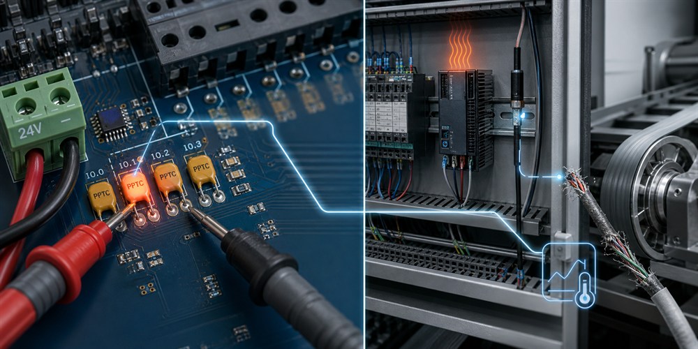
Maintenance engineer Justin once handled a packaging machine where the PPTC tripped repeatedly as soon as the control board powered up. The field team first suspected that the protection component was undersized and planned to install a higher-current part. Justin did not replace it immediately. He first disconnected the external terminal block and found that the control board itself no longer tripped. After reconnecting the harness section by section, he located a cable to a photoelectric sensor that had been worn through by a mechanical edge. The trip was not a selection error; the PPTC was protecting the faulty branch.
The key point of this table is simple: do not interpret every trip as a fuse being too small. If the true cause is a short circuit, increasing the protection rating may allow wires, connectors, or downstream components to carry abnormal current for longer. If the true cause is insufficient thermal derating, replacing the part within the same series without rechecking temperature conditions may only delay the problem.
This mechanism has three implications for industrial control boards.
First, in the normal state, a PPTC is not a zero-resistance device. It remains at low resistance. For low-voltage control power, sensor power, or I/O branches, designers still need to evaluate voltage drop, heat generation, and layout conditions.
Second, when a PPTC trips, it does not permanently melt open like a one-time fuse. Fuzetec's guide to PPTC fuses explains that a PPTC limits fault current by increasing resistance during overcurrent, then recovers after the fault condition is removed. This makes it suitable for overcurrent scenarios that require repeated protection and allow the fault to be cleared.
Third, PPTC behavior is closely tied to temperature. Control cabinets, relays, power modules, power MOSFETs, motor drivers, and sealed enclosures can all raise local temperature. The same load current may produce different trip behavior in an open lab setup versus long-term operation inside a machine.
If you have already started part-number screening, use PPTC selection data to check operating voltage, hold current, trip current, maximum current, trip time, thermal derating, and environmental conditions.
Personnel with equipment safety and electrical measurement experience should follow the equipment maintenance procedure, disconnect power, discharge stored energy, confirm safety, and then check in the following order.
The core of short-circuit troubleshooting is to separate the control board itself from field wiring and external loads. Many industrial control problems are not on the board. They appear in harnesses near moving mechanisms, terminals in humid environments, replaced sensors, or loads that were wired incorrectly during maintenance.
Common overload sources on industrial control boards include:
Machine builder Anna's team once handled an automated inspection machine. Shipment testing was normal, but after the customer added two extra sensor sets to the same 24 V output, the machine tripped after running for several hours each day. When the team brought the control board back, they could not find a short circuit at room temperature. Only after reconstructing the customer's field load did they discover that the steady-state current was already close to the protection device boundary, and that the available hold current dropped as the control cabinet temperature rose. This was not a single component failure; it was a boundary condition caused by load change plus thermal conditions.
In this situation, do not record only the normal current. At minimum, measure standby, typical operation, full load, startup inrush, specific output action, abnormal load, and current after long-term operation separately. Without this data, later selection work easily becomes guesswork.
Fuzetec's PPTC fundamentals also point out that there is an uncertainty region between Ihold and Itrip. Within this region, the device may remain in a low-resistance state or switch to a high-resistance state depending on initial resistance, ambient temperature, and mounting conditions.
This is especially important for industrial control boards. PLC I/O boards, sensor power boards, and equipment control boards operate across many states: standby, output switching, coil pull-in, motor startup, short peak currents, and long-term high temperature. If the normal operating point stays near the boundary between Ihold and Itrip, mass production may see repeated tripping due to PCB copper area, enclosure temperature, lot variation, or installation position.
During selection, confirm at least the following:
If you have organized these conditions, you can use Fuzetec's product search for initial series screening. If the conditions are still incomplete, collect current waveforms and temperature data first, then compare part numbers.
Fuzetec's PPTC selection guide lists thermal derating as a selection factor and reminds engineers to confirm specifications under different ambient temperatures. Fuzetec's PPTC fundamentals also explain that Ihold, Itrip, and the intermediate region are affected by ambient temperature and mounting conditions.
Common thermal risks for industrial control boards include:
Maintenance supervisor David once saw a case where the same control board passed a full day of testing in the repair room, but tripped again during high-load operation in the production-line control cabinet in the afternoon. The team eventually placed temperature logging points near the PPTC and found that a nearby driver component became a local heat source after long-term operation. Before changing the part number, the team adjusted load conditions, reviewed the thermal derating curve again, and included the actual in-machine temperature in the selection data. The problem shifted from 'is the part defective?' to verifiable engineering conditions.
If high temperature is the main risk, review Fuzetec's High Temperature Series product category before confirming the actual datasheet. If control board space is tight, evaluate SMD PPTCs. If the design favors through-hole assembly or a specific board-level process, review Radial Leaded PPTCs.
The purpose of this checklist is not to make selection complicated. It is to prevent decisions based on a single current value. For industrial control boards, faults may come from external wiring, load changes, or the thermal environment. The more complete the data is, the easier it is to determine whether the issue is a circuit problem, a change in use conditions, or a protection device that needs to be reselected.
If you need to translate measured waveforms, ambient temperature, and package limits into part-number screening conditions, contact Fuzetec to discuss PPTC selection. Provide operating voltage, normal load current, possible fault current, maximum ambient temperature, and control board space limits together.
However, a PPTC is not a universal answer for every industrial control fault. If the system requires complete disconnection, extremely fast cutoff, specific safety isolation, very high short-circuit energy withstand capability, or coordination with a protection architecture defined by safety standards, a PPTC should not be used as a direct substitute for other protection devices. These designs should be confirmed through the system architecture, datasheets, standard requirements, and actual testing.
Therefore, the right question is not whether PPTCs are good or bad. The right question is whether this fault mode fits the thermal action and resettable behavior of a PPTC. If the answer is uncertain, evaluate the PPTC together with one-time fuses, power current limiting, OVP devices, system diagnostics, and mechanical heat dissipation.
If the cause is a short circuit, repair the faulty branch first. If the cause is overload or a load change, reconfirm current conditions. If the cause is high temperature or boundary selection, return to Ihold, Itrip, Imax, Vmax, time-to-trip, thermal derating, and package heat dissipation.
Fuzetec's PPTC content and product categories can help engineers build an initial judgment from mechanism, selection parameters, and package options. If you are handling repeated control board tripping, PLC I/O protection, sensor power, or industrial equipment maintenance issues, organize measured data first, then discuss suitable PPTC selection and validation conditions with Fuzetec.
The most dangerous response is to treat repeated tripping as proof that the fuse is simply too small. For industrial control manufacturers, PLC suppliers, machine builders, and maintenance engineers, a protection device trip is a diagnostic signal, not just a failed component. You need to know when it trips, which load branch is active when it trips, whether the ambient temperature has increased, and whether the problem continues after replacement.
This article uses common industrial control board field scenarios to explain how to distinguish overloads, short circuits, startup inrush, insufficient thermal derating, and PPTC selection errors. It also summarizes the data engineers should prepare before sample testing or contacting a supplier, so the final selection can return to the datasheet, thermal derating curves, and real testing instead of experience-based guessing.
Key Takeaways
- An industrial control board fuse that keeps tripping is the result, not the cause. First identify whether it trips immediately at power-up, after running for a while, or only when a specific load operates.
- Short circuits usually come from an abnormal low-resistance path, such as worn harnesses, reverse wiring, component breakdown, solder bridges, terminal contamination, or external load faults.
- Overloads are usually related to load current, startup current, locked-rotor conditions, solenoid valves, or multiple outputs operating at the same time. Measure both waveform shape and duration.
- A PPTC resettable fuse is not a complete open circuit. According to Fuzetec technical articles, when abnormal overcurrent heats the PPTC, its resistance rises to limit current. It returns to low resistance only after the fault is removed and the device cools down.
- Ihold, Itrip, Imax, Vmax, time-to-trip, thermal derating, and package heat dissipation must be reviewed together. Do not judge the design from only one current rating.
Need to confirm available protection device types first? Review Fuzetec's PPTC resettable fuse product category, then return to the troubleshooting flow in this article to organize your voltage, current, fault, and environmental conditions.
Direct Answer: When an Industrial Control Board Fuse Keeps Tripping, Start With 5 Trip Patterns
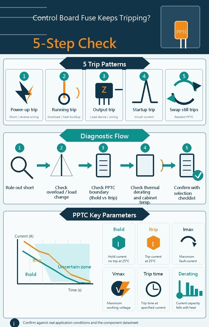
When an industrial control board fuse keeps tripping, the first step is not replacement. The first step is to record the trip pattern. The timing of the trip is usually more valuable than the appearance of the component.- Trips immediately at power-up: prioritize short circuits, reverse wiring, component breakdown, solder bridges, terminal contamination, or external harness problems.
- Trips after running for a while: check overload, heat buildup, control cabinet temperature, PPTC thermal derating, and heat dissipation conditions first.
- Trips only when a specific output operates: check solenoid valves, relays, motors, sensor power, I/O modules, and field wiring.
- Trips during startup: check startup inrush, output capacitor charging, motor startup, coil pull-in current, and the time-to-trip curve.
- Trips repeatedly even after replacing with the same rating: return to Ihold, Itrip, Imax, Vmax, package style, and actual operating temperature for reselection.
Maintenance engineer Justin once handled a packaging machine where the PPTC tripped repeatedly as soon as the control board powered up. The field team first suspected that the protection component was undersized and planned to install a higher-current part. Justin did not replace it immediately. He first disconnected the external terminal block and found that the control board itself no longer tripped. After reconnecting the harness section by section, he located a cable to a photoelectric sensor that had been worn through by a mechanical edge. The trip was not a selection error; the PPTC was protecting the faulty branch.
Industrial Control Board Fuse Keeps Tripping: How to Tell Overload, Short Circuit, Inrush, and Selection Error Apart
Overloads and short circuits are both overcurrent problems, but engineers diagnose them differently. An overload usually means the load current exceeds the design condition for a period of time. A short circuit means an abnormal low-resistance path causes current to rise rapidly. Startup inrush is not always a fault, but if the protection device was selected without considering inrush amplitude and duration, it can still cause nuisance tripping.| Trip Pattern | Possible Cause | Engineering Check | Recommended Next Step |
| Trips immediately at power-up | Short circuit, reverse wiring, component breakdown, solder bridge | Disconnect power and measure downstream resistance after the protection device; disconnect loads and harnesses section by section | Locate the faulty branch; do not simply increase the rating |
| Trips after running for a while | Overload, heat buildup, insufficient heat dissipation | Measure steady-state current, control cabinet temperature, and board-level heat sources | Compare Ihold with the thermal derating curve |
| Trips during startup | Startup inrush, coil pull-in, motor startup | Observe current peak and duration | Compare with the time-to-trip curve |
| Trips only when a specific output operates | External load, field wiring, terminal, or actuator fault | Separate the load, swap channels, and inspect the harness | Confirm whether the issue is a load fault or insufficient protection selection |
| Still trips after replacement | PPTC specification mismatch or thermal conditions not included | Compare Vmax, Imax, Ihold, Itrip, package, and temperature | Reselect the device and run prototype testing |
The key point of this table is simple: do not interpret every trip as a fuse being too small. If the true cause is a short circuit, increasing the protection rating may allow wires, connectors, or downstream components to carry abnormal current for longer. If the true cause is insufficient thermal derating, replacing the part within the same series without rechecking temperature conditions may only delay the problem.
Why Does a PPTC Resettable Fuse Trip?
A PPTC resettable fuse is a recoverable overcurrent protection device. According to Fuzetec's PPTC fundamentals, conductive particles are dispersed in a polymer structure. During normal operation, they form conductive paths. When abnormal current heats the device, the material state changes, the conductive particles separate, and resistance increases sharply.This mechanism has three implications for industrial control boards.
First, in the normal state, a PPTC is not a zero-resistance device. It remains at low resistance. For low-voltage control power, sensor power, or I/O branches, designers still need to evaluate voltage drop, heat generation, and layout conditions.
Second, when a PPTC trips, it does not permanently melt open like a one-time fuse. Fuzetec's guide to PPTC fuses explains that a PPTC limits fault current by increasing resistance during overcurrent, then recovers after the fault condition is removed. This makes it suitable for overcurrent scenarios that require repeated protection and allow the fault to be cleared.
Third, PPTC behavior is closely tied to temperature. Control cabinets, relays, power modules, power MOSFETs, motor drivers, and sealed enclosures can all raise local temperature. The same load current may produce different trip behavior in an open lab setup versus long-term operation inside a machine.
If you have already started part-number screening, use PPTC selection data to check operating voltage, hold current, trip current, maximum current, trip time, thermal derating, and environmental conditions.
Step 1: Rule Out Short Circuits First, and Do Not Repeatedly Power Up for Testing
If a fuse or PPTC trips immediately at power-up, short circuits should be investigated first. This type of problem is usually not suitable for repeated power-up testing, because each attempt can stress the fault point, terminals, PCB traces, or downstream components.Personnel with equipment safety and electrical measurement experience should follow the equipment maintenance procedure, disconnect power, discharge stored energy, confirm safety, and then check in the following order.
- Disconnect power and wait for system energy to discharge before measuring.
- Measure resistance from the protected downstream node to ground, to power, or to adjacent circuits.
- Disconnect external terminals, harnesses, sensors, solenoid valves, motors, and loads, then isolate the fault section by section.
- Check for loose terminals, damaged insulation, water ingress, oil contamination, metal debris, solder bridges, and reverse wiring.
- If the short-circuit current may be high, confirm the protection device Imax and overall system safety design. Do not look only at Ihold.
The core of short-circuit troubleshooting is to separate the control board itself from field wiring and external loads. Many industrial control problems are not on the board. They appear in harnesses near moving mechanisms, terminals in humid environments, replaced sensors, or loads that were wired incorrectly during maintenance.
Step 2: Confirm Whether the Cause Is Overload or a Load Change
If the trip does not happen immediately at power-up, but occurs after the equipment runs for a while or after a specific action cycle, check for overload. Overload does not always mean a short circuit or a failed component. It may mean the load condition has exceeded the original design.Common overload sources on industrial control boards include:
- Multiple sensors or modules sharing the same power branch, with added loads exceeding the original design.
- Aging solenoid valve or relay coils that change pull-in current or holding conditions.
- Small motors, pumps, or actuators that bind, increasing startup or locked-rotor current.
- A low-power field load being replaced with a higher-power model.
- Harness voltage drop or increased contact resistance that causes heating under boundary conditions.
Machine builder Anna's team once handled an automated inspection machine. Shipment testing was normal, but after the customer added two extra sensor sets to the same 24 V output, the machine tripped after running for several hours each day. When the team brought the control board back, they could not find a short circuit at room temperature. Only after reconstructing the customer's field load did they discover that the steady-state current was already close to the protection device boundary, and that the available hold current dropped as the control cabinet temperature rose. This was not a single component failure; it was a boundary condition caused by load change plus thermal conditions.
In this situation, do not record only the normal current. At minimum, measure standby, typical operation, full load, startup inrush, specific output action, abnormal load, and current after long-term operation separately. Without this data, later selection work easily becomes guesswork.
Step 3: Check Whether the PPTC Selection Is Too Close to the Boundary
PPTC selection is often oversimplified as normal current being lower than Ihold. That judgment is too rough. Hold current (Ihold) is the maximum current the device can carry without tripping under rated conditions. Trip current (Itrip) is the minimum current required for the device to trip under rated conditions.Fuzetec's PPTC fundamentals also point out that there is an uncertainty region between Ihold and Itrip. Within this region, the device may remain in a low-resistance state or switch to a high-resistance state depending on initial resistance, ambient temperature, and mounting conditions.
This is especially important for industrial control boards. PLC I/O boards, sensor power boards, and equipment control boards operate across many states: standby, output switching, coil pull-in, motor startup, short peak currents, and long-term high temperature. If the normal operating point stays near the boundary between Ihold and Itrip, mass production may see repeated tripping due to PCB copper area, enclosure temperature, lot variation, or installation position.
During selection, confirm at least the following:
- Whether Ihold is higher than the actual maximum continuous operating current, including thermal derating.
- Whether Itrip is lower than the fault-current range you want to protect against.
- Whether normal startup inrush falls into time-current conditions that may trigger a trip.
- Whether Imax can withstand the possible short-circuit or fault current.
- Whether Vmax matches the highest possible operating voltage or fault voltage at that location.
- Whether package style, copper area, nearby heat sources, and control cabinet temperature have been included in testing.
If you have organized these conditions, you can use Fuzetec's product search for initial series screening. If the conditions are still incomplete, collect current waveforms and temperature data first, then compare part numbers.
Step 4: Check Thermal Derating and Control Cabinet Temperature
Thermal derating is a core selection condition for protection devices on industrial control boards. Ambient temperature affects the available hold current of a PPTC, so field performance cannot be judged from room-temperature testing alone.Fuzetec's PPTC selection guide lists thermal derating as a selection factor and reminds engineers to confirm specifications under different ambient temperatures. Fuzetec's PPTC fundamentals also explain that Ihold, Itrip, and the intermediate region are affected by ambient temperature and mounting conditions.
Common thermal risks for industrial control boards include:
- A sealed control cabinet where heat dissipation differs from lab testing.
- Power modules, relays, MOSFETs, motor drivers, or heatsinks located near the PPTC.
- PCB copper area, pad size, and mounting method affecting heat dissipation.
- Local temperature becoming higher than initial test conditions after long machine operation.
- Summer, outdoor, distribution box, or high-temperature production line environments increasing background temperature.
Maintenance supervisor David once saw a case where the same control board passed a full day of testing in the repair room, but tripped again during high-load operation in the production-line control cabinet in the afternoon. The team eventually placed temperature logging points near the PPTC and found that a nearby driver component became a local heat source after long-term operation. Before changing the part number, the team adjusted load conditions, reviewed the thermal derating curve again, and included the actual in-machine temperature in the selection data. The problem shifted from 'is the part defective?' to verifiable engineering conditions.
If high temperature is the main risk, review Fuzetec's High Temperature Series product category before confirming the actual datasheet. If control board space is tight, evaluate SMD PPTCs. If the design favors through-hole assembly or a specific board-level process, review Radial Leaded PPTCs.
Step 5: Recheck PPTC Suitability With a Selection Data Checklist
Only after short circuits, overload, inrush, and temperature have been initially checked does it make sense to return to PPTC selection. Fuzetec's PPTC selection guide lists operating voltage, hold current, trip current, maximum voltage, maximum current, trip time, thermal derating, environmental conditions, safety approvals, and environmental compliance as selection factors. For industrial control boards, these conditions should be reviewed together.| Selection Data | Why It Matters | Recommended Information to Provide |
| Placement | Voltage and fault current differ by location | Input side, 24 V output, I/O branch, sensor power, or actuator branch |
| Operating voltage | Determines the Vmax screening threshold | Nominal voltage, maximum possible voltage, and voltage that may be seen during faults |
| Normal current | Used to judge Ihold and voltage drop | Standby, typical load, full load, and long-term maximum continuous current |
| Startup and peak current | Used to judge possible nuisance tripping | Startup peak, coil pull-in, motor startup, output capacitor charging, and duration |
| Fault current | Used to judge Itrip and Imax | Overload, short circuit, and current conditions before and after power current limiting |
| Timing requirement | Used to judge whether time-to-trip is suitable | Normal startup time, allowable fault duration, and downstream component withstand limits |
| Thermal conditions | Used to judge thermal derating and nuisance-trip risk | Maximum control cabinet temperature, nearby heat sources, board layout, and heat dissipation conditions |
| Package limits | Affects assembly process, heat dissipation, and available space | SMD, radial, height, PCB area, and maintenance requirements |
The purpose of this checklist is not to make selection complicated. It is to prevent decisions based on a single current value. For industrial control boards, faults may come from external wiring, load changes, or the thermal environment. The more complete the data is, the easier it is to determine whether the issue is a circuit problem, a change in use conditions, or a protection device that needs to be reselected.
If you need to translate measured waveforms, ambient temperature, and package limits into part-number screening conditions, contact Fuzetec to discuss PPTC selection. Provide operating voltage, normal load current, possible fault current, maximum ambient temperature, and control board space limits together.
When Is a PPTC Suitable, and When Should It Be Re-Evaluated?
A PPTC resettable fuse is suitable for overcurrent scenarios that require repeated protection and restored conduction after the fault is cleared. DigiKey TechForum's PPTC application note also lists industrial automation equipment and PLC controllers as typical application scenarios, and describes PPTC behavior as low resistance in normal operation, high resistance after overcurrent heating to limit current, and recovery after the fault is removed.However, a PPTC is not a universal answer for every industrial control fault. If the system requires complete disconnection, extremely fast cutoff, specific safety isolation, very high short-circuit energy withstand capability, or coordination with a protection architecture defined by safety standards, a PPTC should not be used as a direct substitute for other protection devices. These designs should be confirmed through the system architecture, datasheets, standard requirements, and actual testing.
Do Not Ignore Aging, Frequent Trips, and Physical Damage
Long-term use conditions also matter. DigiKey TechForum's summary of PPTC failure scenarios mentions long-term overcurrent, temperature factors, current surges that are too large or too long, frequent operation, physical damage, and aging as factors that may affect PPTC condition. These points do not mean every application will experience the same issue, but they remind engineers to keep trip counts, environmental conditions, and faulty branch information in maintenance records.Therefore, the right question is not whether PPTCs are good or bad. The right question is whether this fault mode fits the thermal action and resettable behavior of a PPTC. If the answer is uncertain, evaluate the PPTC together with one-time fuses, power current limiting, OVP devices, system diagnostics, and mechanical heat dissipation.
FAQ: Industrial Control Board Fuse Tripping Questions Engineers Often Ask
Can I directly replace an industrial control board fuse that keeps tripping with a larger rating?
Not recommended. Repeated tripping may indicate a short circuit, overload, startup inrush, insufficient thermal derating, or mismatched component specifications. Directly using a higher rating may expose the faulty branch to abnormal current for longer. First confirm the trip pattern, measure current and temperature, then judge from the datasheet and test results.How can I tell whether it is a short circuit or an overload?
Immediate tripping at power-up usually points first to a short circuit, reverse wiring, component breakdown, or harness problem. Tripping after a period of operation, or after a specific load operates, more often requires checking overload, startup inrush, load changes, and heat buildup. The most reliable approach is to disconnect loads section by section, measure downstream resistance after the protection device, and record current waveforms.How long does a PPTC take to recover after tripping?
Recovery time depends on whether the fault has been removed, whether the device temperature has dropped, ambient temperature, and mounting conditions. Fuzetec technical articles describe a PPTC as returning to a low-resistance state after the fault is removed and the device cools down. Actual recovery behavior should still be confirmed using the datasheet and prototype testing.How should I read Ihold and Itrip?
Ihold is the hold current, used to judge the device's ability to avoid tripping under specified conditions. Itrip is the trip current, used to judge the current threshold at which the device enters a high-resistance state under specified conditions. Both must be reviewed with ambient temperature, thermal derating, mounting conditions, startup inrush, fault current, and the time-to-trip curve.Why can a high-temperature control cabinet cause PPTC nuisance tripping?
A PPTC is a temperature-dependent device. Higher control cabinet temperature, nearby heat sources, PCB heat dissipation conditions, or package differences can all move the device closer to the trip state. Designers should check thermal derating using the highest actual ambient temperature, not only room-temperature test results.Is a PPTC suitable for PLC outputs or sensor power?
It may be suitable, depending on the protection goal. If the requirement is resettable overcurrent protection and the fault can be cleared, a PPTC can be evaluated. If the requirement is complete disconnection, extremely fast cutoff, or specific safety isolation, the protection architecture and relevant standards should be reviewed again.Conclusion: Identify the Cause of Tripping Before Discussing Selection
When an industrial control board fuse keeps tripping, the real problem is not which part to replace. The real question is why it trips. First distinguish immediate tripping at power-up, tripping after operation, tripping during startup, or tripping only when a specific load operates. Then use resistance measurement, section-by-section disconnection, current waveforms, and temperature data to locate the cause.If the cause is a short circuit, repair the faulty branch first. If the cause is overload or a load change, reconfirm current conditions. If the cause is high temperature or boundary selection, return to Ihold, Itrip, Imax, Vmax, time-to-trip, thermal derating, and package heat dissipation.
Fuzetec's PPTC content and product categories can help engineers build an initial judgment from mechanism, selection parameters, and package options. If you are handling repeated control board tripping, PLC I/O protection, sensor power, or industrial equipment maintenance issues, organize measured data first, then discuss suitable PPTC selection and validation conditions with Fuzetec.
Sources
- Fuzetec, PPTC Fundamentals
- Fuzetec, Complete Guide to Selecting PPTC Resettable Fuses
- Fuzetec, PPTC Fuse Explained: A Guide to Automatically Resettable Overcurrent Protection
- Fuzetec, PPTC Resettable Fuse Product Category
- DigiKey TechForum, How PPTCs Use an Automatic Recovery Mechanism to Prevent Overcurrent and Typical Application Scenarios
- DigiKey TechForum, What Possible Failure Conditions Can Affect PPTC Resettable Fuses?
Tag