Table of Contents
An engineer’s field guide to Ihold, Itrip, voltage, fault current, resistance, derating, and the I-t curve
Fuzetec Circuit Protection Application Engineering TeamWhy You Can’t Choose the Right Part If You Can’t Read the Datasheet
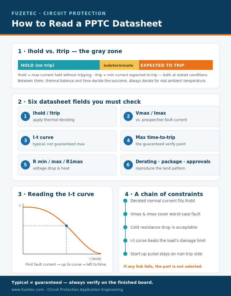
A design can look correct at room temperature and still nuisance-trip inside a sealed enclosure. The usual cause is not a defective resettable fuse; it is a selection made from one headline number. Reading a PPTC datasheet means treating the device as a thermal component whose current capability changes with ambient temperature, copper area, airflow, mounting, and event duration.Hold current and trip current do different jobs. Ihold is the maximum current the device is specified to carry without tripping under the stated reference conditions. Itrip is the minimum current expected to make it transition toward its high-resistance state under those same conditions. The region between them is not a precise switching threshold. Thermal balance decides the outcome, so time and environment matter.
A PPTC also does not open like a one-time fuse. When a fault heats the polymer, resistance rises sharply and limits current; some leakage remains. The device resets only after the fault and power are removed long enough for it to cool. That behavior is useful, but only when the protected circuit tolerates the residual current and recovery behavior.
When reading a PPTC datasheet, use it as a chain of constraints: normal current must fit the derated hold capability; voltage and prospective fault current must remain within absolute ratings; cold resistance must not create excessive voltage drop; and the time-current curve must protect the load before its damage limit. If any link fails, the part is not selected.
Six Datasheet Fields You Must Check
1. Ihold and Itrip
When reading a PPTC datasheet, start with the test conditions printed in the definitions or notes. A value specified at 23°C or 25°C in still air is not automatically valid at 70°C beside a power MOSFET. Apply the manufacturer’s thermal derating curve to Ihold. Do not simply select Ihold equal to the load’s nominal current; include tolerance, steady peaks, ambient range, and board heating.Do not read Itrip as an instantaneous trip point. Above Itrip, the device is expected to trip, but the delay depends strongly on fault-current multiple and temperature. Between Ihold and Itrip, the outcome is application-dependent. That gray zone is why a current margin and an I-t check are necessary.
2. Rated Voltage and Maximum Fault Current
A PPTC datasheet defines Vmax as the highest voltage the PPTC is designed to withstand under the datasheet’s stated conditions. Imax is the maximum fault current it can withstand at the rated voltage without damage. Both limits must be satisfied together. Compare Imax with the source’s prospective short-circuit current, not with the normal load current.A 24 Vdc rail can still deliver tens or hundreds of amperes from a low-impedance battery or bulk capacitor. If the available fault current exceeds Imax, the device may arc, carbonize, or fail unpredictably. Use source impedance, battery capability, wiring, and upstream protection to estimate the worst case.
3. Time-Current Curve (I-t Curve)
When reading a PPTC datasheet, the I-t curve plots fault current on the horizontal axis and time to trip on the vertical axis, usually on logarithmic scales. Each curve corresponds to a part number. Find the expected fault current on the x-axis, move vertically to the selected device curve, then move horizontally to read the typical trip time.Typical is not guaranteed maximum. For a safety or damage-limited design, use a specified maximum time-to-trip point when available and validate production spread, temperature, and source variation. The curve is most useful for comparing candidates and checking whether a fault is far enough from the ambiguous Ihold-to-Itrip region.
4. Maximum Time to Trip
A PPTC datasheet’s electrical table often provides one verification point as a current-and-time pair, such as ‘8 A, 5 s maximum.’ Read the two columns together. It does not mean the part always trips within five seconds at every overcurrent. This guaranteed point is valuable for acceptance testing and bounding a known fault condition.5. Resistance: Rmin, Rmax, and R1max
Cold resistance sets the normal voltage drop and heat: Vdrop = Iload × R, and Ploss = Iload² × R. Use the appropriate maximum resistance for worst-case design, not the typical value. R1max commonly represents the maximum resistance after a defined trip or soldering history, so it can be more realistic for a fielded assembly than an initial typical value.Check whether the added drop affects brownout margin, battery runtime, measurement accuracy, or high-speed signal integrity. A current rating that passes thermally can still be unacceptable electrically.
6. Thermal Derating, Package, Approvals, and Test Notes
When reading a PPTC datasheet, the derating chart translates room-temperature Ihold into usable current at the actual ambient temperature. Also confirm package size, pad or lead geometry, solder profile, operating range, flammability rating, and required agency recognition. PCB copper can change heat dissipation, so reproduce the manufacturer’s recommended land pattern and validate the finished board.Finally, reading a PPTC datasheet includes its footnotes. They define still-air conditions, conditioning time, resistance measurement timing, and whether data are typical or guaranteed. Many selection errors happen because the table was read but the notes were not.
Using the Curve to Judge Response Time
Suppose a candidate sees a 6 A fault. On a log-log I-t chart, locate 6 A on the x-axis, trace upward to that part’s curve, then trace left to the y-axis. If the intersection is near 0.4 s, treat that as a typical estimate unless the datasheet explicitly labels it as a limit. Repeat at the minimum credible fault current, because a weaker source usually produces the slowest trip.Next compare trip time with the load’s damage boundary. A connector, cable, MOSFET, or battery cell has its own current-versus-time tolerance. The PPTC curve should lie on the protective side of that boundary across the relevant fault range. Also check start-up current: its amplitude and duration must stay on the non-trip side with margin.
Remember that a warmer PPTC trips sooner and holds less current; a cold PPTC may carry more current and trip more slowly. Bench testing only at 25°C can therefore miss both nuisance-trip risk at high temperature and inadequate protection at low temperature.
A Real Selection Walkthrough
Consider a 24 Vdc controller with 0.75 A continuous current, a 1.25 A start-up pulse lasting 300 ms, a 65°C internal ambient, and an estimated 8 A minimum fault current. The protected input should be current-limited within 2 s. This is an illustrative workflow, not a recommendation for a specific part number.Step 1 — Derated hold current. Assume the candidate family’s 65°C derating factor is 0.60. Required room-temperature Ihold is at least 0.75 / 0.60 = 1.25 A. Add design margin for load tolerance and local heating; a 1.5 A class candidate may be a better starting point than a 1.25 A part.
Step 2 — Start-up immunity. Plot 1.25 A at 0.3 s against the candidate’s I-t curve. The point must remain comfortably below the trip curve across hot units and repeated starts. Ihold alone cannot answer this pulse question.
Step 3 — Absolute limits. Confirm Vmax is at least 24 Vdc with system transients handled separately, and Imax exceeds the highest prospective short-circuit current. If a capacitor or battery can produce more than the assumed 8 A, recalculate using that higher value.
Step 4 — Fault response. At the minimum 8 A fault, read the candidate’s typical curve and maximum trip specification. Reject it if the worst-case response can exceed the input’s 2 s damage limit.
Step 5 — Voltage drop. If R1max is 0.12 Ω, the conservative steady drop at 0.75 A is 0.09 V and loss is about 0.068 W. Check these values at maximum load and temperature against rail margin and PCB heating.
Step 6 — Validate hardware. Test low, room, and high temperature; minimum and maximum supply; start-up repetitions; faults; reset time; and worst-case component tolerance. Record current and PPTC surface temperature. The datasheet narrows the candidates; the application test closes the design.
FAQ
Q1. Is trip current the exact current at which a PPTC switches off?
No. Itrip is defined under stated conditions and does not mean instantaneous disconnection. Trip time depends on current, ambient temperature, mounting, and prior thermal history.Q2. What happens between Ihold and Itrip?
Depending on thermal balance and duration, the device may continue conducting or eventually trip.Q3. Can I choose a PPTC using only Ihold?
No. You must also verify thermal derating, Vmax, Imax, resistance, I-t response, package constraints, and the protected load’s damage limit.Q4. Why did the board nuisance-trip below the room-temperature Ihold?
The PPTC may be hotter than the measured room ambient because of nearby components, limited airflow, copper geometry, or repeated events. Use local device temperature and the derating curve.Q5. Does a PPTC fully disconnect a fault?
No. It enters a high-resistance state and limits current, but residual current remains. Confirm that the load can tolerate it.Q6. Is the I-t curve guaranteed?
It is commonly typical unless the datasheet says otherwise. Use maximum time-to-trip limits where provided and verify the final circuit.Conclusion
Reading a PPTC datasheet correctly is less about memorizing Ihold and Itrip than understanding their conditions. Select from derated normal current, verify voltage and available fault current, calculate worst-case drop from resistance, and use the I-t curve against both start-up pulses and the load’s damage boundary.For a broader foundation, review how a PPTC resettable fuse works, then compare the full selection guide and common overcurrent protection selection traps. Together, these checks turn a catalog shortlist into an evidence-based protection design.
Need a Specification Review?
Send Fuzetec your operating-current profile, ambient range, supply voltage, prospective fault current, required trip time, package preference, and reset expectations. Our circuit protection application team can help identify candidate PPTC families and define a practical validation plan. Contact Fuzetec for a specification consultation.Technical Sources
Tag